Cooperative adaptive lighting system using vehicle to target or object communication

a technology of adaptive lighting and target, applied in traffic control systems, transportation and packaging, instruments, etc., can solve the problems of poor distance accuracy of adb camera, adb camera system only detects objects, and the accuracy is generally not obtained, so as to enhance the shape and light intensity of the headlamp beam, accurate distance measurement, and accurate measurement

Active Publication Date: 2017-08-15
VALEO NORTH AMERICA
View PDF24 Cites 26 Cited by
  • Summary
  • Abstract
  • Description
  • Claims
  • Application Information

AI Technical Summary

Benefits of technology

[0010]Another object of the invention is to provide an accurate distance measurement for controlling and enhancing an accurate headlamp beam shape and light intensity.
[0011]Another object of the invention is to provide at least one or a plurality of telematics control units that are adapted to detect objects equipped with similar telematics control units in a predetermined range, such as in a 360 degree field-of-view fashion. Another object of the invention is to provide a telematics control unit that is configured and adapted to accurately measure distances between a vehicle and another vehicle, target, pedestrian, object or infrastructure in order to control a headlamp assembly in response thereto, thereby enhancing accurate beam shaping and generation and intensity.
[0012]Another object of the invention is to provide a V2X application that provides position accuracy of 1.5 meter or better and communication ranges of at least 300 meters.

Problems solved by technology

There are various disadvantages of some of the prior art approaches which include poor distance accuracy with a camera, which is typically a mono-camera, in particular at higher vehicle speeds.
Accurate distance measurements are critical for headlamp ADB, and with camera systems of the past, such accuracy was generally not obtained.
Another problem with prior art camera systems is that ADB camera systems would only detect objects within its field of view.
Specific to pedestrians, at night, if the pedestrian is in a zone of poor lighting, the pedestrian might not be detected by a camera system at all, which may lead to a dangerous or hazardous condition for the pedestrian.

Method used


Image

  • Cooperative adaptive lighting system using vehicle to target or object communication
  • Cooperative adaptive lighting system using vehicle to target or object communication
  • Cooperative adaptive lighting system using vehicle to target or object communication

Examples


Embodiment Construction

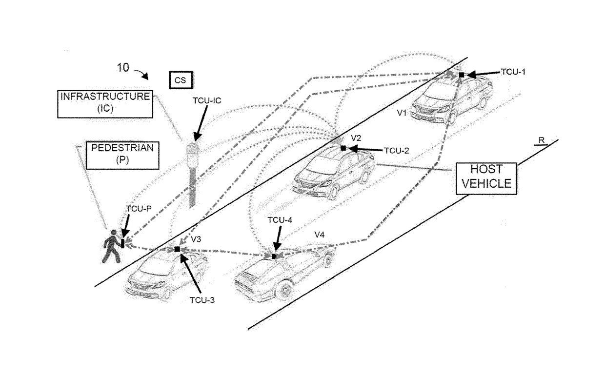
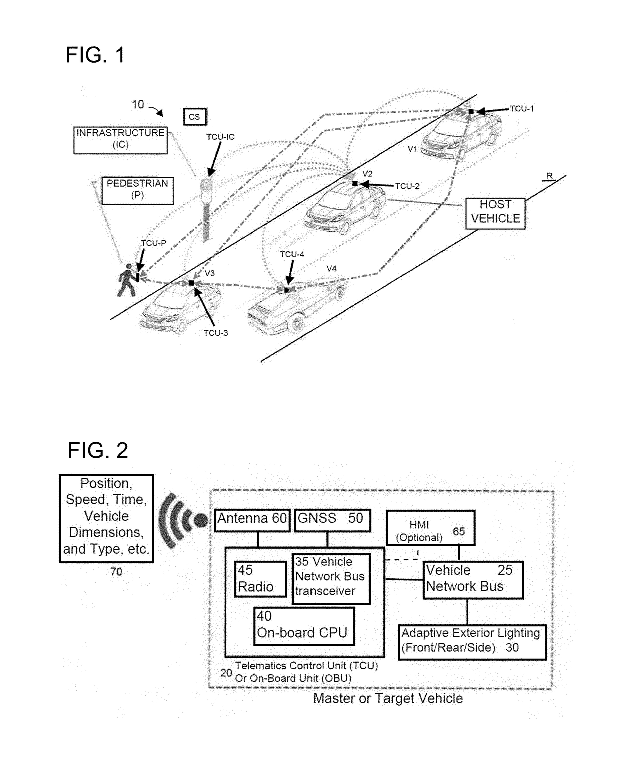
[0077]FIG. 1 illustrates a cooperative adaptive lighting system 10 having four vehicles V1, V2, V3, and V4 on a roadway R, and a pedestrian P near the road. An infrastructure component IC is also located near the road R. The vehicles V1-V4 are equipped with Telematics Control Units (TCU) 20 (FIG. 2) described later herein, namely TCU-1-TCU-4, respectively, which may comprise computers, cell phones, pad-computers, and the like, together with transmitting and receiving antennas (shown in FIG. 2). The pedestrian P is equipped with a TCU device, which could a smartphone with compatible transmit radio and positioning capability and a dedicated wearable V2X transmitter, designated as TCU-P, but it should be understood that the TCU-P could simply be a transmitter, and the infrastructure component IC is equipped with a TCU, designated as TCU-IC. The TCU may comprise or be an on-board unit (OBU) having the same components. For ease of description and understanding, they will both be referred...


PUM


Abstract

A cooperative adaptive lighting system for motor vehicles in which a vehicle transmits its geographic coordinates and receives similar coordinates from other vehicles, pedestrians, and stationary warning devices. Using the coordinates, the vehicle computes distances, and relative position more specifically, to those entities. When the distances become sufficiently small, indicating that the entities fall within headlight range, the vehicle alters its headlight beams to either (1) throw more light on an entity, (2) reduce light reaching the entity as appropriate, or (3) change a lighting pattern as appropriate.

Description

BACKGROUND OF THE INVENTION[0001]1. Field of the Invention[0002]This invention relates to a cooperative adaptive lighting system using a vehicle-to-vehicle, vehicle-to-infrastructure, vehicle-to-pedestrian, vehicle-to-target or other vehicle-to-object (hereinafter collectively referred to as V2X) communication.[0003]2. Description of the Related Art[0004]In the past, various approaches have been used to control headlights which are also known as headlamps on vehicles. For example, a typical solution was to use a camera-based adaptive headlamp, also known as adaptive driving beam (ADB) or a glare-free headlamp. The headlamps' lights change lighting shape and intensity distribution profile based on oncoming or preceding vehicles or possibly upon the detection of a pedestrian, all of which is captured by the camera. In many countries, especially in Europe, advanced driving beams are regulated and it is anticipated that they will soon be regulated in the United States.[0005]There are va...

Claims


Application Information

Patent Timeline
Patent Type & Authority Patents(United States)
IPC IPC(8): B60Q1/02B60Q1/20H05B37/02B60Q1/14G01S19/13
CPCB60Q1/143H05B37/0254H05B37/0227H05B37/0272B60Q1/20G01S19/13B60Q2300/31B60Q2300/32B60Q2300/42B60Q2300/45B60Q1/085B60Q1/46G08G1/005G08G1/096716G08G1/09675G08G1/096783G08G1/096791G08G1/162B60Q2300/056B60Q2300/305B60Q2300/312B60Q2300/335B60Q2300/41B60Q2300/47H05B47/115H05B47/19Y02B20/40H05B47/18
Inventor TALEB-BENDIAB, AMINE
Owner VALEO NORTH AMERICA
Why Eureka
Try Eureka