
Process for phase-derived range measurements

a phase-derived and range-derived technology, applied in the field of radar systems, can solve problems such as reducing the safety margin built into radar to cope with interference, and achieve the effect of reducing the signal-to-noise ratio (snr) and data ra

Active Publication Date: 2005-02-10
RAYTHEON CO
View PDF36 Cites 30 Cited by
  • Summary
  • Abstract
  • Description
  • Claims
  • Application Information

AI Technical Summary

Benefits of technology

The present invention features a technique that provides a high precision range measurement at reduced signal-to-noise ratio (SNR) and data rate so that radar system objectives in a main beam jamming and / or multiple target environment can be achieved.
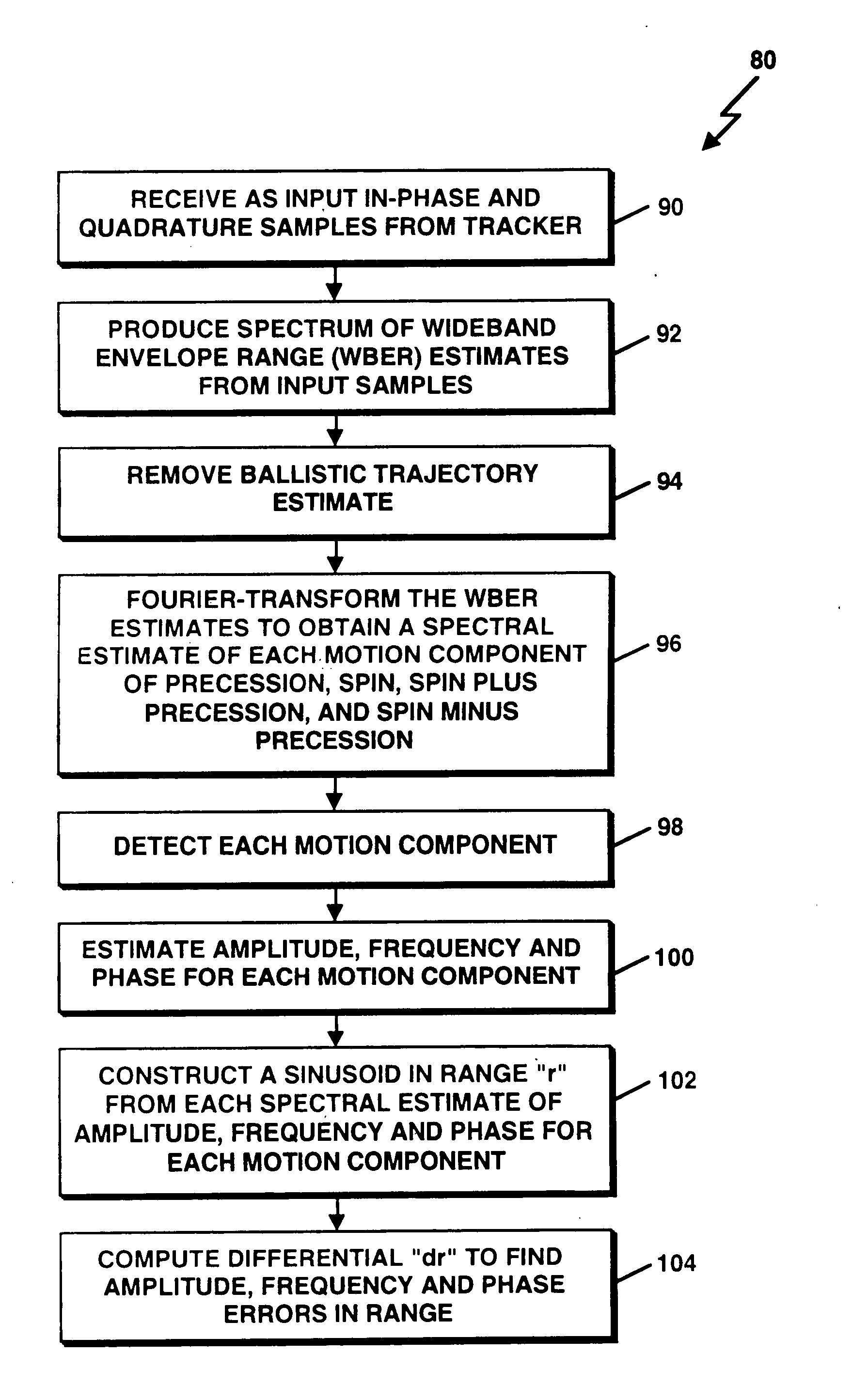
Particular implementations of the invention may provide one or more of the following advantages. Through the use of the range phase determination of the present invention it is possible to observe small motions in body dynamics of targets, e.g. re-entry vehicles and decoys, and measure range of such targets with the precision of phase. Moreover, it is possible to reduce the data rate and signal-to-noise ratio requirements of phase-derived range measurement by using wideband envelope range (WBER).

Problems solved by technology

Such unambiguous phase measurements require a significant amount of radar system resources, more specifically, higher signal-to-noise (SNR) and data rates, thus reducing the safety margin built into the radar to cope with interferers such as main beam jamming or an increased number of targets.

Method used


Image

  • Process for phase-derived range measurements
  • Process for phase-derived range measurements
  • Process for phase-derived range measurements

Examples


Embodiment Construction

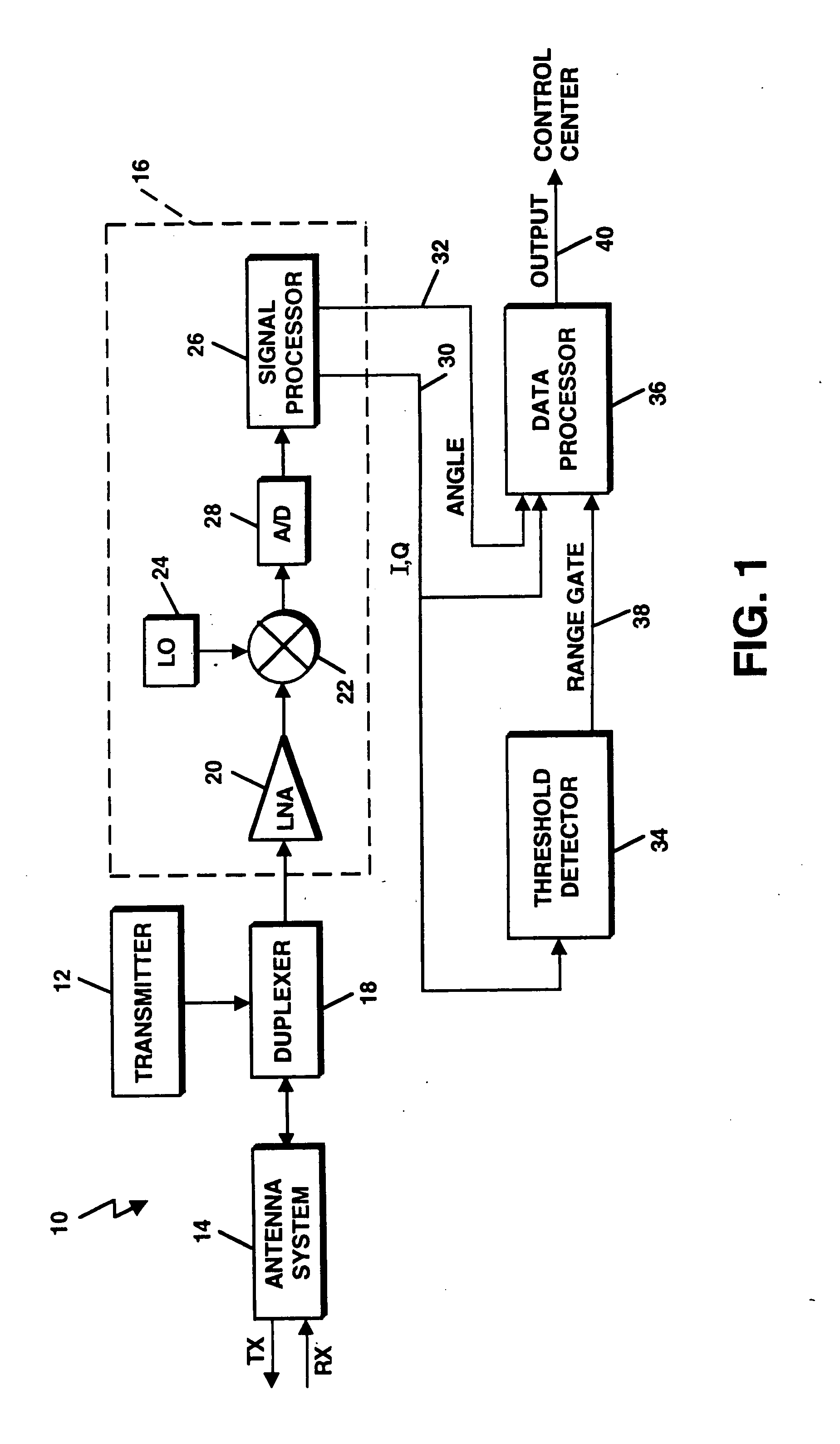
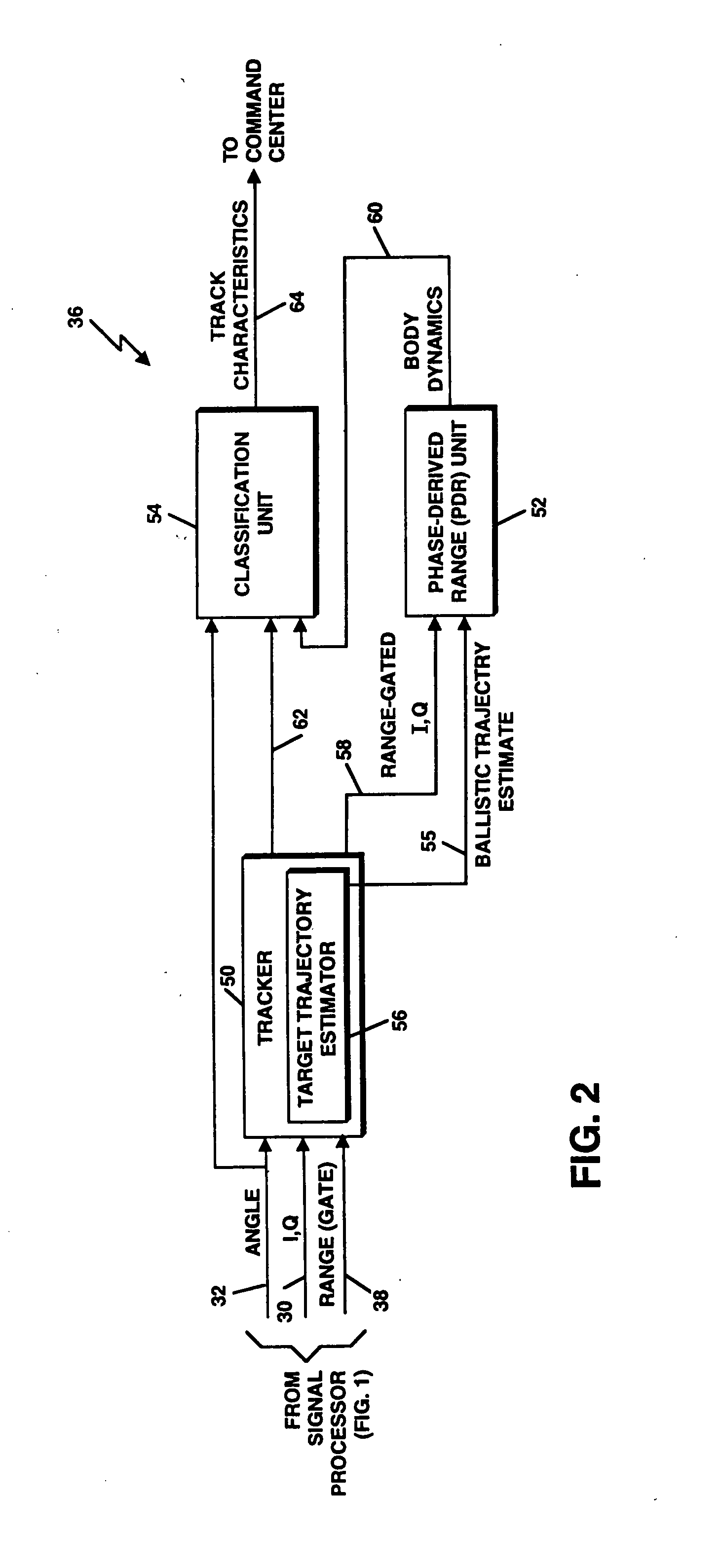
Referring to FIG. 1, a tracking radar system 10 is shown. The tracking radar system 10 may be a ground-based radar system, but could be employed on a ship or in an aircraft or other airborne or non-airborne vehicle as well. In one embodiment, the tracking radar system 10 is implemented as a pulse Doppler tracking radar system. The tracking radar system 10 includes a transmitter 12, the output of which is delivered to an antenna system 14 for radiation in the form of a transmit beam. The antenna system 14 collects echo (return) signals received from a target. The return signals are processed by a receiver 16 to detect the presence of the target and determine its location in range and in angle. The antenna system 14 can include a mechanically or electronically rotating antenna. A duplexer 18 coupled to the transmitter 12, receiver 16 and antenna system 14 allows the antenna system 14 to be used on a time-shared basis for both transmitting and receiving.

Still referring to FIG. 1, th...


PUM


Abstract

A method and apparatus for determining range of a radar target is provided. Signal samples based on returns of a target during tracking are processed to produce a wideband envelope range estimate for components of target motion. The components of target motion include precession and spin motion. Ambiguous phase values are measured. An unambiguous phase value indicative of range is produced from the wideband envelope range estimate and measured ambiguous phase values.

Description

BACKGROUND The invention relates generally to radar systems, and more particularly, to radar range measurement. Typically, a radar system (or more simply a radar) tracks a target's centroid position to obtain an estimate of ballistic flight characteristics for range determination. To obtain estimates of ballistic flight, radar systems typically use filters such as Kalman filters of relatively high order to produce range measurement data. Such filtering is designed to model only a target's ballistic trajectory. Therefore, it is possible to track and measure range from target trajectory quite accurately. To observe small variations in range due to motions other than ballistic motion, it is necessary to sample target returns in a manner that ensures that phase change measured from one radar pulse to the next is unambiguous. Such unambiguous phase measurements require a significant amount of radar system resources, more specifically, higher signal-to-noise (SNR) and data rates, thus ...

Claims


Application Information

Patent Timeline
IPC IPC(8): G01S7/41G01S13/58G01S13/66
CPCG01S7/415G01S13/66G01S13/584
Inventor STEUDEL, FRITZ
Owner RAYTHEON CO
Learn More