Monitoring device and method using echo signals

a technology of monitoring device and echo signal, which is applied in the direction of measuring device, using reradiation, instruments, etc., can solve the problems of difficulty in ensuring the accuracy required for reliable measurements in positioning the transceiver uni

Inactive Publication Date: 2005-03-10
ROBERT BOSCH GMBH
View PDF1 Cites 24 Cited by
  • Summary
  • Abstract
  • Description
  • Claims
  • Application Information

AI Technical Summary

Benefits of technology

[0019] For example, the closer the obstacle is to the vehicle, i.e., the more obtuse the angle is at which it reflects a cross-echo, the greater is the influence of the distance between the transceiver units on the cross-echo propagation time. At the same time, propagation times of the cross-echoes which are much greater than those of the direct echoes are obtained in reflection on a linear obstacle in such a case. It

Problems solved by technology

This problem has resulted in echo-signal monitoring devices for motor vehicles being installed so far practically only in new vehicles by vehicle manufacturers.
In

Method used


Image

  • Monitoring device and method using echo signals
  • Monitoring device and method using echo signals
  • Monitoring device and method using echo signals

Examples


Embodiment Construction

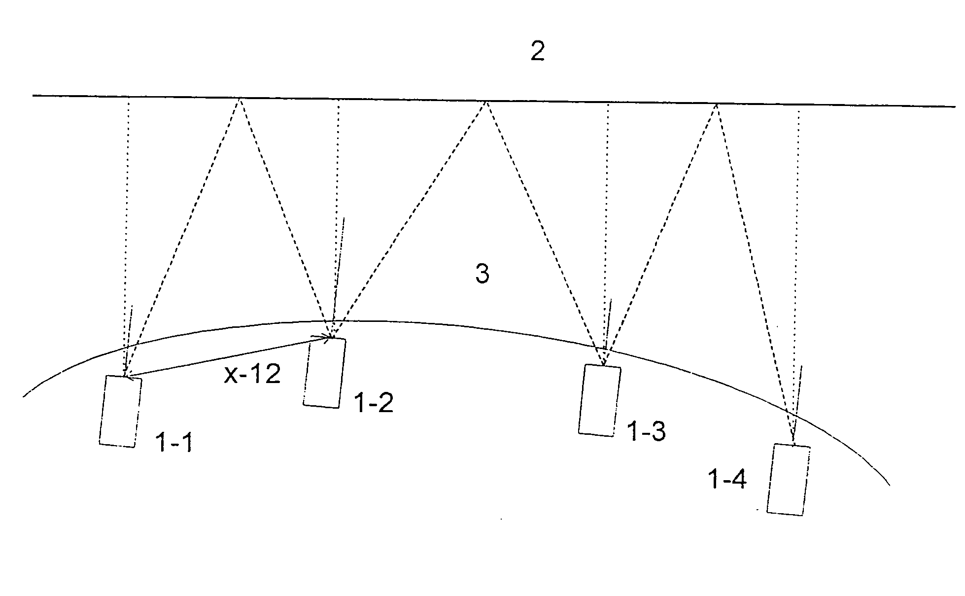
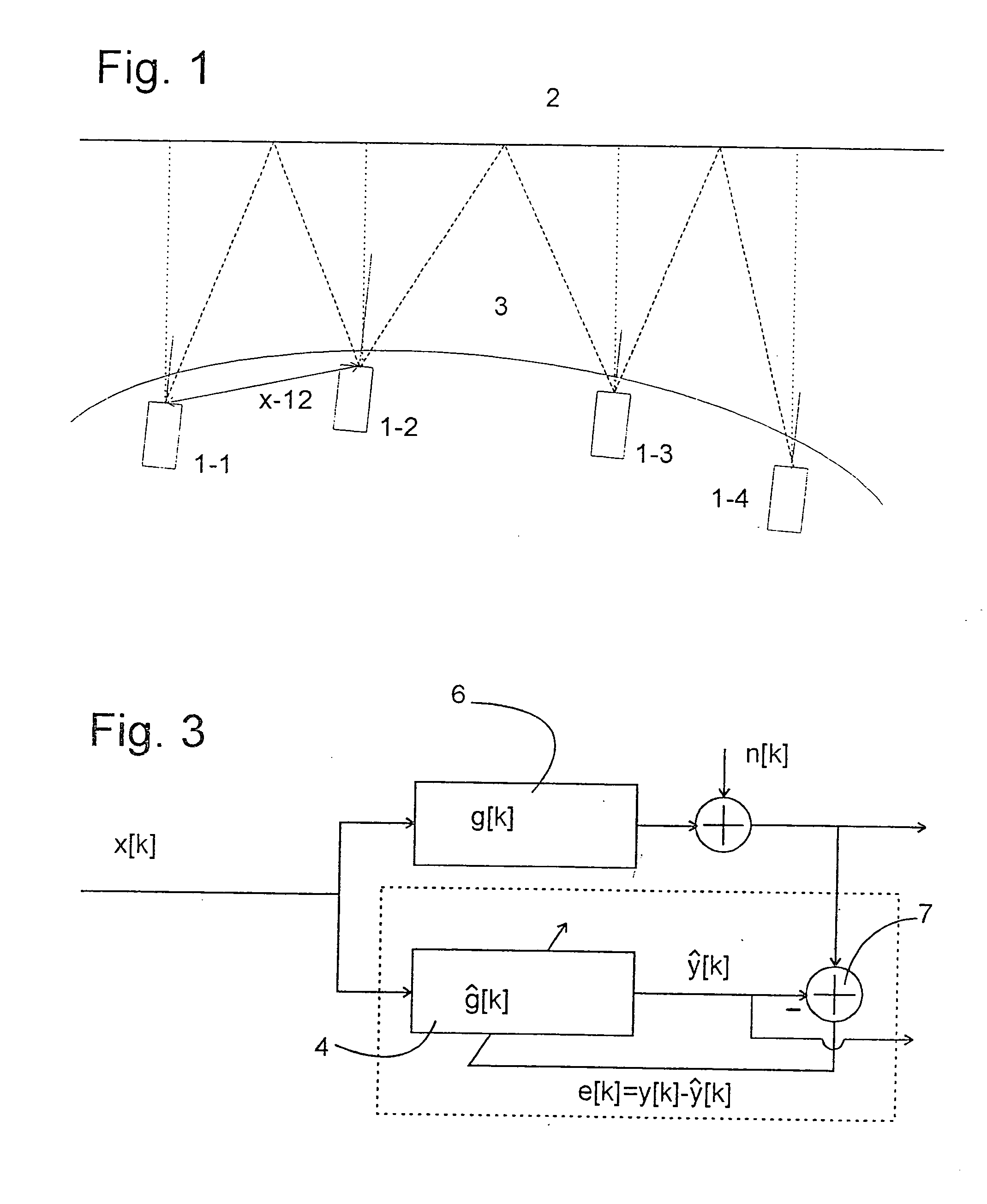
[0024]FIG. 1 shows a system of four transceiver units 1_1, 1_2, 1_3 and 1_4 of an echo-signal monitoring device with respect to a wall 2 representing a linear obstacle to be detected with the echo-signal monitoring device. The echo-signal monitoring device is built into a motor vehicle. The curved line along which transceiver units 1_1 through 1_4 are distributed may represent, for example, the curve of a bumper 3 of the vehicle, as seen from above.

[0025] Transceiver units 1_1 through 1_4 send pulse-shaped echo signals at points in time which are determined randomly by a control unit (not shown in the figure) and these signals are reflected by wall 2. A direct echo is reflected by the corresponding points on wall 2, whose surface normal intersects one of transceiver units 1_1, . . . , 1_4. Cross-echoes are reflected by points 2_ik on wall 2, where the angle of incidence of a signal pulse from transceiver unit 1_i is equal to the angle of reflection to unit 1_k. If T_ik denotes the ...


PUM


Abstract

An echo-signal monitoring device having a plurality of transceiver units for transmitting signals and receiving the echoes reflected by an external object and an analyzer unit for estimating the distance from the monitoring device to the external object on the basis of the received echoes is characterized in that the device has an operating mode for calculating the relative position of the transceiver units from one another on the basis of the reflected echoes.

Description

FIELD OF THE INVENTION [0001] The present invention relates to a device and a method for monitoring the environment with the help of echo signals. BACKGROUND INFORMATION [0002] Devices and methods for monitoring the environment with the help of echo signals are used in particular in motor vehicles, where obstacles in the environment of the vehicle are detected with the help of transceiver units, in particular for ultrasound, radar, and infrared signals. A plurality of such transceiver units may be fixedly mounted on the vehicle body, and if necessary a warning signal is generated to warn the driver of the vehicle of a potentially hazardous approach to an obstacle in complex traffic situations such as parking. [0003] Such a monitoring device and a method for operating same are referred to in DE 40 23 538 A1, for example. [0004] The accuracy with which such devices function depends to a great extent on the accuracy with which the relative positions of the plurality of transceiver unit...

Claims


Application Information

Patent Timeline
IPC IPC(8): G01S7/52G01S7/526G01S15/87G01S15/931
CPCG01S7/52004G01S7/526G01S15/876G01S2015/938G01S15/931G01S2013/9353G01S15/878G01S2013/932
Inventor KLINNERT, ROLANDZOTT, CHRISTIANSCHMIDT, HAUKESCHLUFF, STEFFENWIRNITZER, BERNHARD
Owner ROBERT BOSCH GMBH
Why Eureka
Try Eureka