
Flexible and collapsible construction geometry tool

Inactive Publication Date: 2005-04-19
ABBEY JOHN D
View PDF27 Cites 12 Cited by
  • Summary
  • Abstract
  • Description
  • Claims
  • Application Information

AI Technical Summary

Benefits of technology

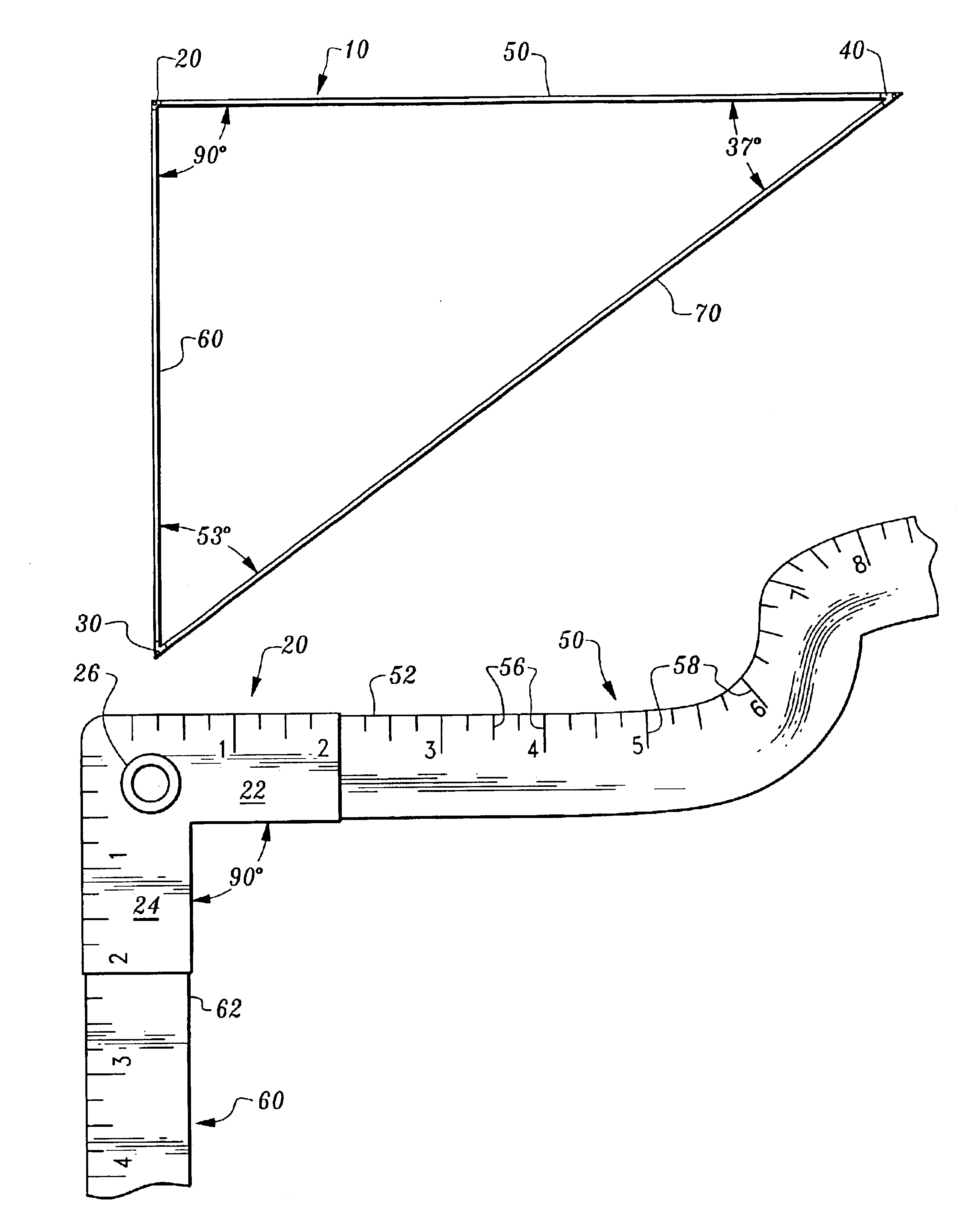
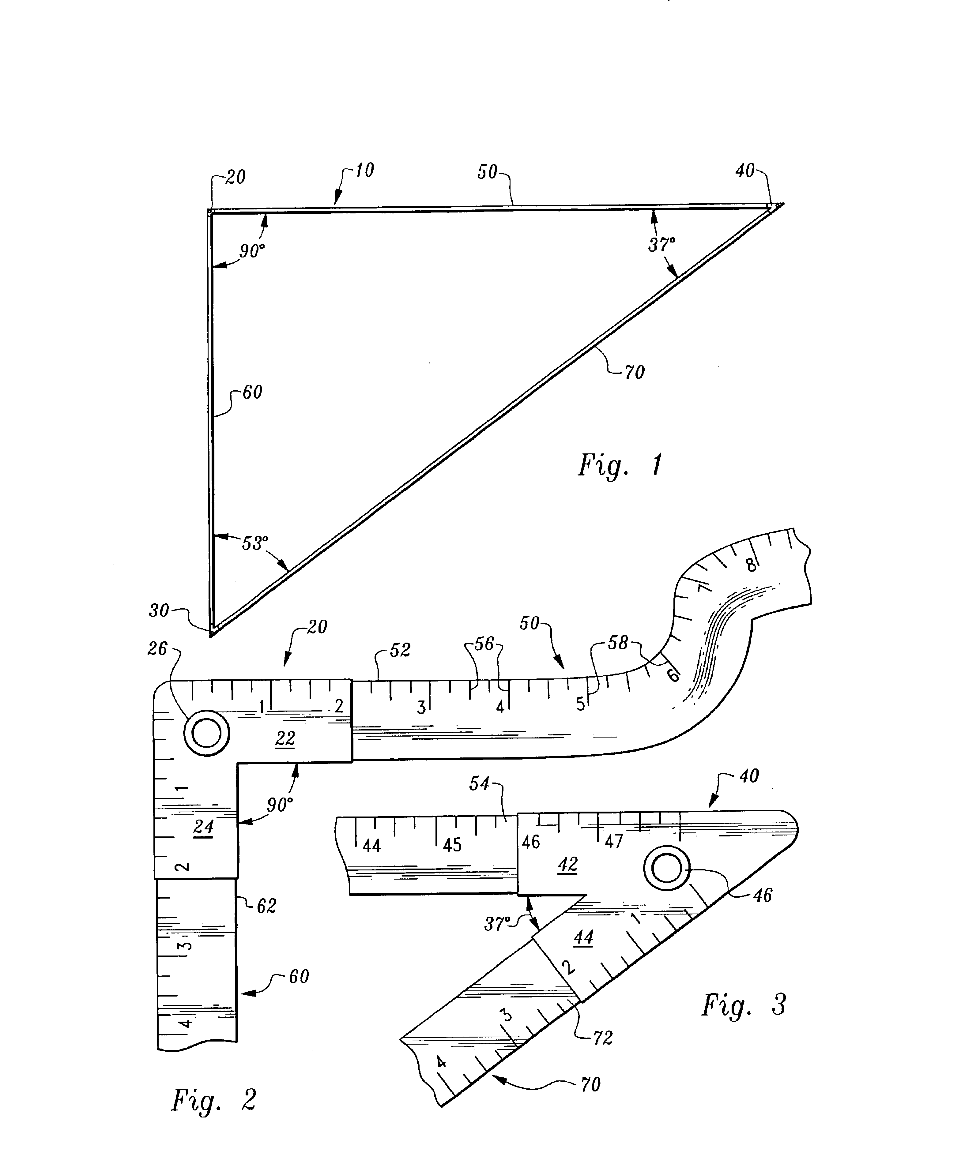
[0009]This invention provides a tool for quickly and easily laying out square corners and other corners of a foundation with precise angular measurements. The tool is in the form of a triangle formed of elongate flexible inelastic strands, such as flexible measuring tape strands. The triangular tool has a first corner, second corner and third corner each mutually spaced from each other and coupled together by a first flexible strand, a second flexible strand and a third flexible strand. The strands have precise lengths so that when each of the strands are fully extended angles adjacent the corners and between adjacent strands are precisely provided.
[0013]Accordingly, a primary object of the present invention is to provide a tool to assist in precisely laying out corners of a foundation of a structure to be built.
[0014]Another object of the present invention is to provide a foundation corner layout tool which can be utilized by a single user to efficiently and precisely lay out corners of a foundation of a structure to be built.
[0015]Another object of the present invention is to provide a construction geometry tool which provides both precise angular measurements and precise distance measurements.
[0016]Another object of the present invention is to provide a construction geometry tool which can be collapsed into a small space.
[0017]Another object of the present invention is to provide a construction geometry tool which is lightweight.

Problems solved by technology

Even when a carpenter's square is precisely utilized, most commonly some degree of error results when the sides of the structure adjacent the square corner are extended.
Even a large protractor will have the same deficiency as the carpenter's square, in that when the sides of the structure adjacent the corner are extended, they will rarely precisely have the measurement desired.
While this technique is effective, it requires a significant amount of time to implement, significantly delaying the process of laying out and forming the foundation of the structure.
While this technique is generally effective, it takes a significant amount of time to implement in practice.

Method used


Image

  • Flexible and collapsible construction geometry tool
  • Flexible and collapsible construction geometry tool
  • Flexible and collapsible construction geometry tool

Examples


Embodiment Construction

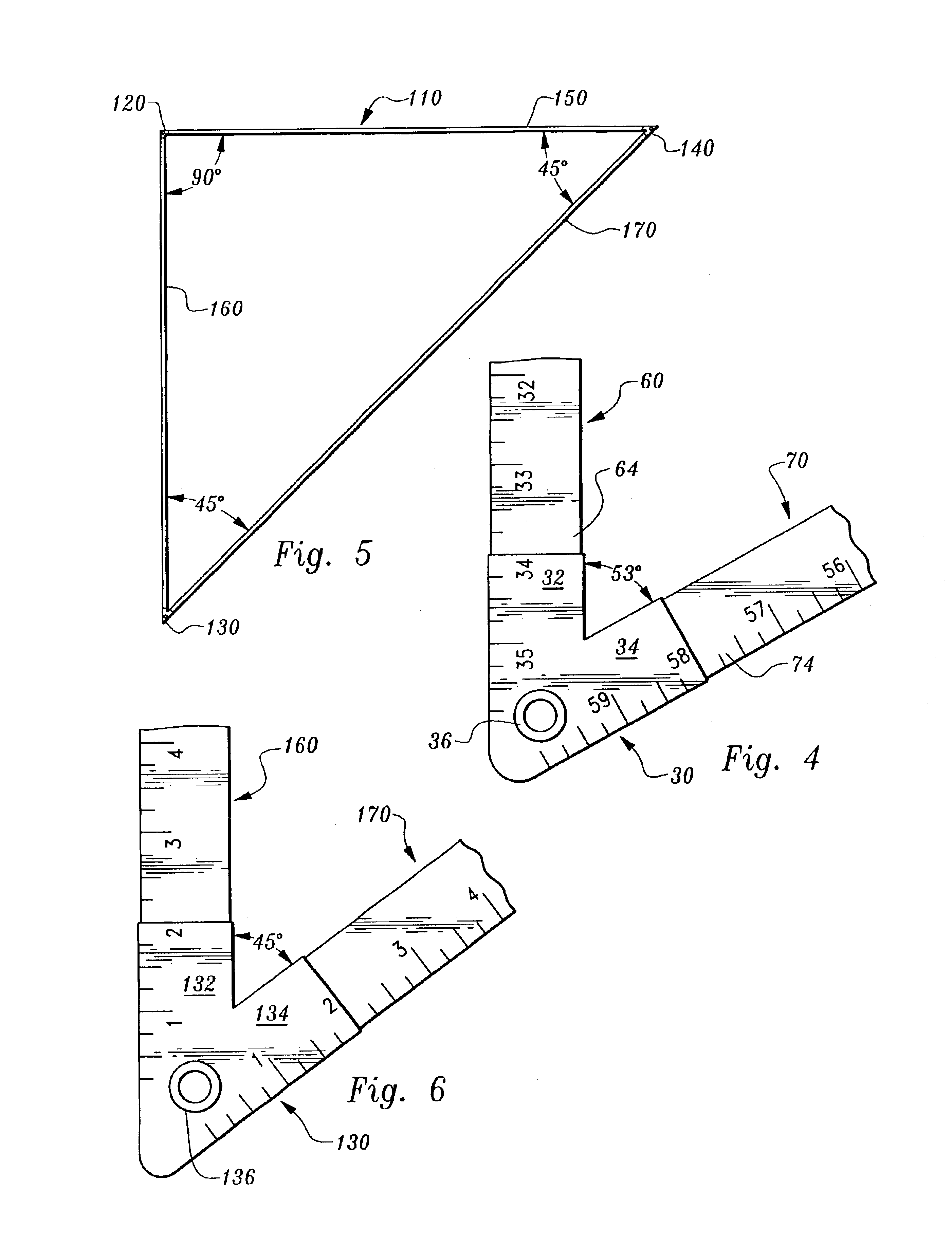
[0027]Referring to the drawings, wherein like reference numerals represent like parts throughout the various drawing figures, reference numeral 10 is directed to a construction geometry tool (FIG. 1) which can be utilized to quickly and precisely lay out corners of a foundation of a structure (FIG. 7) with proper angular measurements. The tool 10 is formed of tapes 50, 60, 70 which are flexible but which are inelastic to resist elongation thereof. The tool 10 can thus be collapsed into a small space and later deployed with each of the tapes 50, 60, 70 fully extended so that desired angular measurements are provided by corners of the triangle represented by the tool 10.

[0028]In essence, and with particular reference to FIGS. 1-4, basic details of the construction geometry tool 10 of this invention are described. The construction geometry tool 10 is preferably generally in the form of three separate tape measures joined together at corners thereof to form a triangle having desired ang...


PUM


Abstract

A tool is provided for laying out precise angles in construction of structures such as a foundation. The tool includes three corners including a first corner, a second corner and a third corner. Each of the corners are spaced from each other by separate strands including a first strand, a second strand and a third strand. Each of the strands are inelastic so that when fully extended they have a precise length. The lengths of the three strands are precisely provided so that the tool is provided in the form of a triangle with angular measurements of each of the corners precisely as desired. Preferably, one of the corners measures exactly 90° to facilitate the forming of a structure with a foundation having corners which measure precisely 90°.

Description

FIELD OF THE INVENTION[0001]The following relates to tools for use in constructing foundations and other portions of structures with desired geometries. More particularly, this invention relates to tools for assisting in the layout of foundations of structures so that angles in the foundations of the structures, and particularly square corners of the structures, are precisely square or otherwise angularly measured precisely as desired.BACKGROUND OF THE INVENTION[0002]In laying out the foundations of structures, and particularly residential structures and related structures, it is important that the foundation be square, or otherwise have a geometry precisely matching a desired geometry for the foundation and for the structure. Most commonly, corners of the foundation are square corners measuring 90°. While numerous tools are in existence for assisting in the layout of 90°“square” corners, each of these tools has certain drawbacks.[0003]“Carpenter's square” type devices are known whi...

Claims


Application Information

Patent Timeline
IPC IPC(8): E04G21/18
CPCE04G21/1833
Inventor ABBEY, JOHN D.
Owner ABBEY JOHN D
Learn More