Eureka AIR delivers breakthrough ideas for toughest innovation challenges, trusted by R&D personnel around the world.

Sensing and control device and method for a weight measurement device

Pending Publication Date: 2020-01-30
KONINKLJIJKE PHILIPS NV
View PDF5 Cites 0 Cited by
  • Summary
  • Abstract
  • Description
  • Claims
  • Application Information

AI Technical Summary

Benefits of technology

The present invention provides a cost-effective solution for measuring the weight change of material, such as food during cooking, using a low-level ADC. The load on the device prior to the loading of the material is recorded and converted to a DC level. This results in a more precise measurement of the material weight change, without being impacted by the weight of the load unit. This invention can be used in various weight measurement devices, such as those in pharmacy and material science, where precise but affordable measurements are needed.

Problems solved by technology

In practise, it is difficult to configure a load gauge arrangement to directly weigh the food, but instead it often is configured to weigh a cooking vessel or even the whole cooking appliance including the food.
Reducing the load requires either complicate mechanical isolation or placing the load gauge arrangement closer to the food but also closer to the harsh cooking environment, which may interfere with the sensing accuracy.
Using a high precision ADC with a larger dynamic range is actually the common practice at present for its simplicity but with the expensive ADC increasingly wasted on the growing weight of today's appliances.

Method used


Image

  • Sensing and control device and method for a weight measurement device
  • Sensing and control device and method for a weight measurement device
  • Sensing and control device and method for a weight measurement device

Examples


Embodiment Construction

[0044]The following description explains the present invention with reference to an application in a cooking device, to which the present invention is, however, not limited.

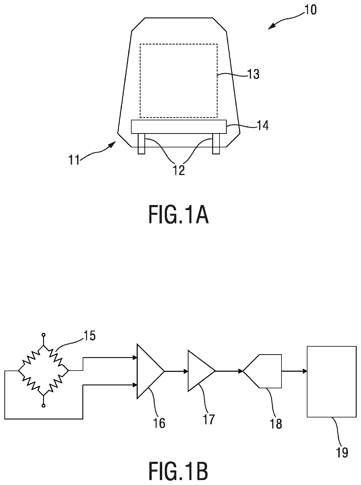
[0045]FIG. 1A shows a schematic diagram of a conventional cooking device 10. In a common implementation of the weighing function in such a cooking device 10 the weight measurement device 11 comprising load gauges 12 (in general a load measurement unit comprising one or more load measurement elements such as load gauges or load cells) is arranged at the bottom of the cooking device 10. The weight measurement device 11 thus measures the whole cooking device 10 including the cooked food arranged in a load unit 13, which in this embodiment is a compartment of the cooking device 10, to stay away from the harsh cooking environment. The cooking device 10 further comprises a sensing and control device 14, which is shown in more detail in FIG. 1B. According to this embodiment the sensing and control device 14 is coupled t...


PUM


Abstract

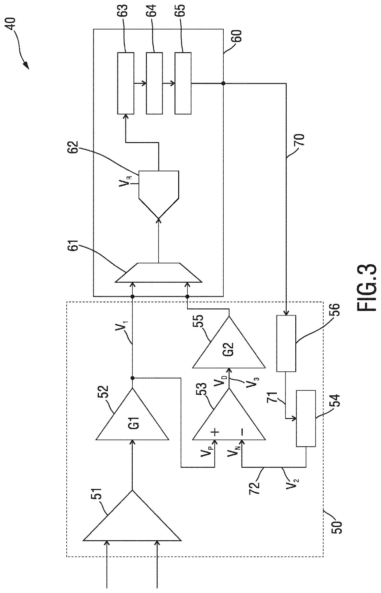
The present invention relates to a sensing and control device (40) and method for a weight measurement device (30) comprising a load unit for loading material to be weighted. To enable precise measurement with less expensive components, said sensing and control device comprises analog circuitry (50) configured to receive a weight measurement signal, convert the received weight measurement signal into a first voltage signal, subtract a second voltage signal representing the weight of at least the load unit without being loaded with material to be weighted from the first voltage signal when the load unit is loaded with material to be weighted to generate a third voltage signal representing the weight of the material to be weighted, and control circuitry (60) configured to receive the first voltage signal while the load unit is not loaded with material to be weighted, convert the first voltage signal into a first digital signal, and generate a pulse width modulated, PWM, signal having a pulse width representing the weight measured by the load unit while not being loaded with material to be weighted, and further configured to convert the third voltage signal into a second digital signal representing the weight measurement of the material to be weighted. The analog circuitry (50) is configured to generate the second voltage signal from the PWM signal generated by the control circuitry, wherein the voltage level of the second voltage signal is proportional to the pulse width of the PWM signal.

Description

FIELD OF THE INVENTION[0001]The present invention relates to a sensing and control device and method for a weight measurement device comprising a load unit for loading material to be weighted. The present invention relates further to a weight measurement device and a cooking device.BACKGROUND OF THE INVENTION[0002]Nowadays, a trend in home kitchen appliances is to automate the cooking processes to free consumers from lengthy waiting times, intervention and failed outcome. Monitoring weight change of food during cooking has been proven as a good indicator of food doneness status in many dry cooking methods (e.g. grill, roast, bake, frying, etc.). This is often realized with some load gauge arrangement (or, more generally, a weight measurement device comprising a load unit into which material to be weighted can be loaded) to transduce the gravity to electrical signal, which is amplified to match the range of an analog-to-digital converter (ADC) given by the reference voltage and then ...

Claims


Application Information

Patent Timeline
IPC IPC(8): G01G23/16G01G3/13G01G19/52A47J36/32
CPCG01G19/52G01G3/13A47J36/32G01G23/166G01G19/56
Inventor FENG, HAITAOLUO, ZHONGCHI
Owner KONINKLJIJKE PHILIPS NV
Why Eureka
Eureka Blog
Learn More