A disconnection automatic detection device for the production of communication optical fiber and cable

An automatic detection device and technology of communication optical fibers, applied in the field of optical fiber and cable production, can solve the problems of relying on labor, low detection efficiency, low manual detection efficiency, etc., and achieve the effect of high degree of automation and high efficiency

Active Publication Date: 2020-11-24
四川特旺通信科技有限公司
View PDF6 Cites 0 Cited by
  • Summary
  • Abstract
  • Description
  • Claims
  • Application Information

AI Technical Summary

Problems solved by technology

[0005] The existing optical fiber production equipment does not have a real-time optical fiber disconnection detection device, and generally requires follow-up detection, and the detection process needs to rely heavily on manual work, not only the detection efficiency is low, but also the quality of optical fiber production cannot be guaranteed. More importantly, , manual detection is not only inefficient, but also the accuracy of detection is difficult to meet people's needs. There is an urgent need for a device that can automatically detect disconnection in the optical fiber production process

Method used


Image

  • A disconnection automatic detection device for the production of communication optical fiber and cable
  • A disconnection automatic detection device for the production of communication optical fiber and cable
  • A disconnection automatic detection device for the production of communication optical fiber and cable

Examples


Embodiment

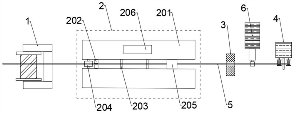
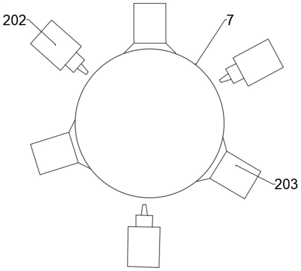
[0028] like figure 1 and figure 2 As shown, the present invention provides a disconnection automatic detection device for the production of communication optical fiber and cable, including a production line platform 5, the leftmost end of the production line platform 5 is provided with a pay-off device 1, and the right side of the pay-off device 1 is provided with There are two-stage optical fiber detection components 2, the right side of the two-stage optical fiber detection component 2 is provided with a caliper 3, the right side of the caliper 3 is provided with a sheath processing device 6, and the uppermost part of the production line platform 5 is A take-up machine 4 is arranged at the right end, and an optical fiber 7 to be tested is arranged above the production line platform 5 .

[0029] The specific embodiment of the present invention is to produce optical fiber cables on the production line platform 5. First, the pay-off device 1 starts to release the optical fibe...


PUM

PropertyMeasurementUnit
diameteraaaaaaaaaa

Abstract

The invention discloses a line breakage automatic testing device for production of a communication optical fiber cable. The device comprises a production line platform. The leftmost end of the production line platform is provided with a pay-off device. The right side of the pay-off device is provided with a two-stage optical fiber detecting assembly. The right side of the two-stage optical fiber detecting assembly is provided with a diameter measuring instrument. The right side of the diameter measuring instrument is provided with a sheath processing device. The rightmost end of a production line platform is provided with a wire winding machine. A to-be-tested optical fiber is arranged above the production line platform. According to the line breakage automatic detecting device, a two-stage optical fiber testing assembly is utilized; and measurement is performed according to a comparison method in which a returning signal is received by means of a backward scattering method and a manner of utilizing optical-magnetic modulation and converting modulated light to an electric signal. Because the measuring facility for the electric signal is more accurate, the breakage condition of theoptical fiber cable can be accurately tested. Furthermore the line breakage automatic testing device can perform comprehensive testing on signal damping and signal transmission capability of the optical fiber and fills a gap of testing line breakage in the optical fiber production process in prior art, thereby realizing high popularization value.

Description

technical field [0001] The invention relates to the technical field of optical fiber cable production, in particular to an automatic disconnection detection device for communication optical fiber cable production. Background technique [0002] Fiber optics are similar to coaxial cables, except without the mesh shield. In the center is the glass core for light propagation. In a multimode optical fiber, the diameter of the core is 15 mm to 50 mm, which is roughly equivalent to the thickness of a human hair. The diameter of the single-mode fiber core is 8 mm to 10 mm. The core is surrounded by a glass jacket with a lower refractive index than the core to keep the fiber inside the core. On the outside is a thin plastic jacket to protect the envelope. Optical fibers are usually bundled and protected by a jacket. The fiber core is usually a double-layer concentric cylinder with a small cross-sectional area made of quartz glass. It is brittle and easy to break, so an additiona...

Claims


Application Information

Patent Timeline
Patent Type & Authority Patents(China)
IPC IPC(8): G01R31/54G01R31/00G01N21/47G01N21/17
CPCG01N21/1717G01N21/47G01N2021/1727G01N2021/4709G01R31/00G01R31/50
Inventor 杜长军李新华
Owner 四川特旺通信科技有限公司
Why Eureka
Try Eureka