Clamp structure used for parallel face milling of glass mold

A glass mold and face milling technology, which is applied in the field of tooling and fixtures, can solve the problems of difficulty in parallel planes, low processing efficiency, waste of electric energy, etc., meet the requirements of industrialized enlarged production, improve milling efficiency, and reduce operating intensity. Effect

Active Publication Date: 2015-06-17
ORI MOLD TECH SUZHOU
View PDF6 Cites 23 Cited by
  • Summary
  • Abstract
  • Description
  • Claims
  • Application Information

AI Technical Summary

Problems solved by technology

This method of parallel face milling of glass molds has at least the following disadvantages: First, the processing efficiency is low, because there is a pause period after the milling machine completes the end face milling of the glass mold. The time it takes to reverse the 180° re-clamping; second, because a half-mold (glass mold is usually composed of a pair of two halves that cooperate with each other) requires two clamping, so the labor intensity of the workers is high; its Third, due to the existence of two clampings, it is difficult to guarantee the quality of the milling process. The specific performance is that the parallel surface is difficult to achieve the desired degree of parallelism; Fourth, due to the pause period of the milling machine, the electric energy supporting the work of the milling machine is wasted.
[0005] The above-mentioned drawbacks are caused by the lack of clamps with reasonable structure in essence. For this reason, the applicant has carried out a literature search in order to expect to obtain the enlightenment that can solve the above-mentioned technical problems from the literature, but in the patents and non-patents disclosed so far There is no corresponding technical information in the literature, so the applicant made a useful design, and finally formed the technical solution to be introduced, and carried out a simulation test in the applicant's factory area under strict confidentiality measures. It turned out to be feasible

Method used


Image

  • Clamp structure used for parallel face milling of glass mold
  • Clamp structure used for parallel face milling of glass mold

Examples


Embodiment

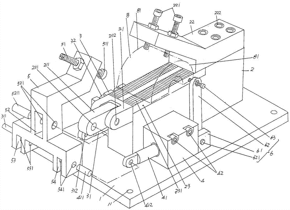
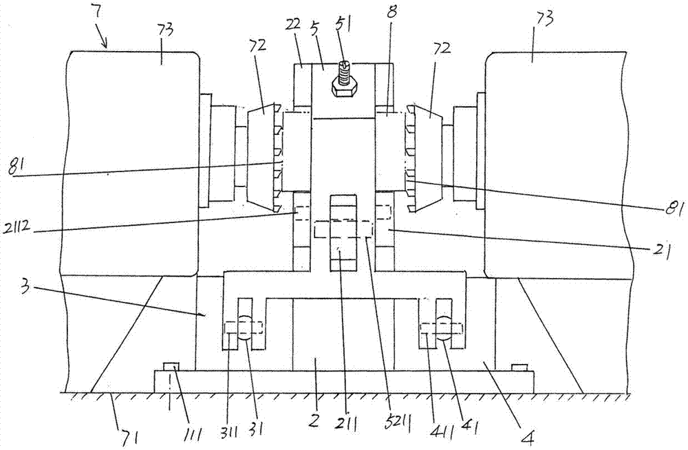
[0022] See figure 1 , a bottom plate 1 with a rectangular shape (cuboid in this embodiment) and made of metal is provided, and a bottom plate installation and fixing hole 11 is provided at each of the four corners of the bottom plate 1, and the bottom plate fixing screw 111 is used for use. Base plate 1 and workbench 71 of milling machine 7 ( figure 2 shown) fixed.

[0023] A pedestal 2 is fixed on the upward side of the bottom plate 1 in use, and a shaft connecting seat 21 is formed on the upper part of one end of the pedestal 2. figure 1 As shown, the connecting seat 21 of the connecting plate protrudes from the end face of the aforementioned one end of the base 2 in a horizontal state, and a connecting plate 211 is pivotally connected to the connecting seat 21 through a pin 2112. The connecting plate The top of the other end of 211 is fixed with a fixed support seat 22, and at the middle part of the base 2 and on the side facing upwards, a glass mold seat plate 23 is fix...


PUM


Abstract

The invention provides a clamp structure used for parallel face milling of a glass mold, and belongs to the technical field of tool clamps used for manufacture of the glass mold. The clamp structure comprises a bottom plate, a base, a first action cylinder, a second action cylinder, and a movable bearing base. The base is fixed on the upward side of the bottom plate, a connection shaft plate connecting base is formed on the upper portion of one end of the base, a fixed bearing base is fixed on the upper portion of the other end of the base, and a glass mold base plate is fixed in the middle of the base. The first action cylinder and the second action cylinder are located on two sides of the base respectively and fixed on the base. The upper portion of the movable bearing base corresponds to the fixed bearing base, the middle of the movable bearing base is connected with the connection shaft plate connecting base, one end of the lower portion of the movable bearing base is connected with the first action cylinder, the other end of the lower portion of the movable bearing base is connected with the second action cylinder, the upper portion of the movable bearing base corresponds to the upper portion of one end of the glass mold base plate in a vacant state, and the fixed bearing base faces one end of the movable bearing base and corresponds to the upper portion of the other end of the glass mold base plate. Milling efficiency is high, industrialization widened production requirements are met, operation intensity of workers is reduced, the parallelism of parallel faces of the glass mold can be guaranteed, and energy-saving effects are ideal.

Description

technical field [0001] The invention belongs to the technical field of fixtures for manufacturing glass molds, and in particular relates to a fixture structure for parallel face milling of glass molds. Background technique [0002] Fixtures play a very important role in the production of industrial products, and the processing of glass molds is no exception. The so-called fixture refers to the special equipment or tool used to clamp or position the workpiece in machining to meet certain process requirements. Fixtures usually need to meet the requirements of no interference during product production, accurate and reliable positioning, and convenient operation. Since the fixtures have the exclusive characteristics of manufacturing a certain product, the degree of generalization is low, and they are often made by manufacturers who produce mechanical products. Glass mold manufacturers are also mostly equipped with various fixtures in a self-made way. [0003] Before milling th...

Claims


Application Information

Patent Timeline
Patent Type & Authority Patents(China)
IPC IPC(8): B23Q3/08
Inventor 戈剑鸣
Owner ORI MOLD TECH SUZHOU
Why Eureka
Try Eureka