Humeral Implant Having A Floating Bearing

a technology of humeral implants and bearings, which is applied in the field of humeral implants, can solve the problems of damage or defective external surface and achieve the effect of improving the stability and stability of the humeral head

Active Publication Date: 2013-08-08
BIOMET MFG CORP
View PDF4 Cites 23 Cited by
  • Summary
  • Abstract
  • Description
  • Claims
  • Application Information

AI Technical Summary

Problems solved by technology

It is not uncommon for the exterior surface of the humeral head to become damaged or defective over time.

Method used


Image

  • Humeral Implant Having A Floating Bearing
  • Humeral Implant Having A Floating Bearing
  • Humeral Implant Having A Floating Bearing

Examples


Embodiment Construction

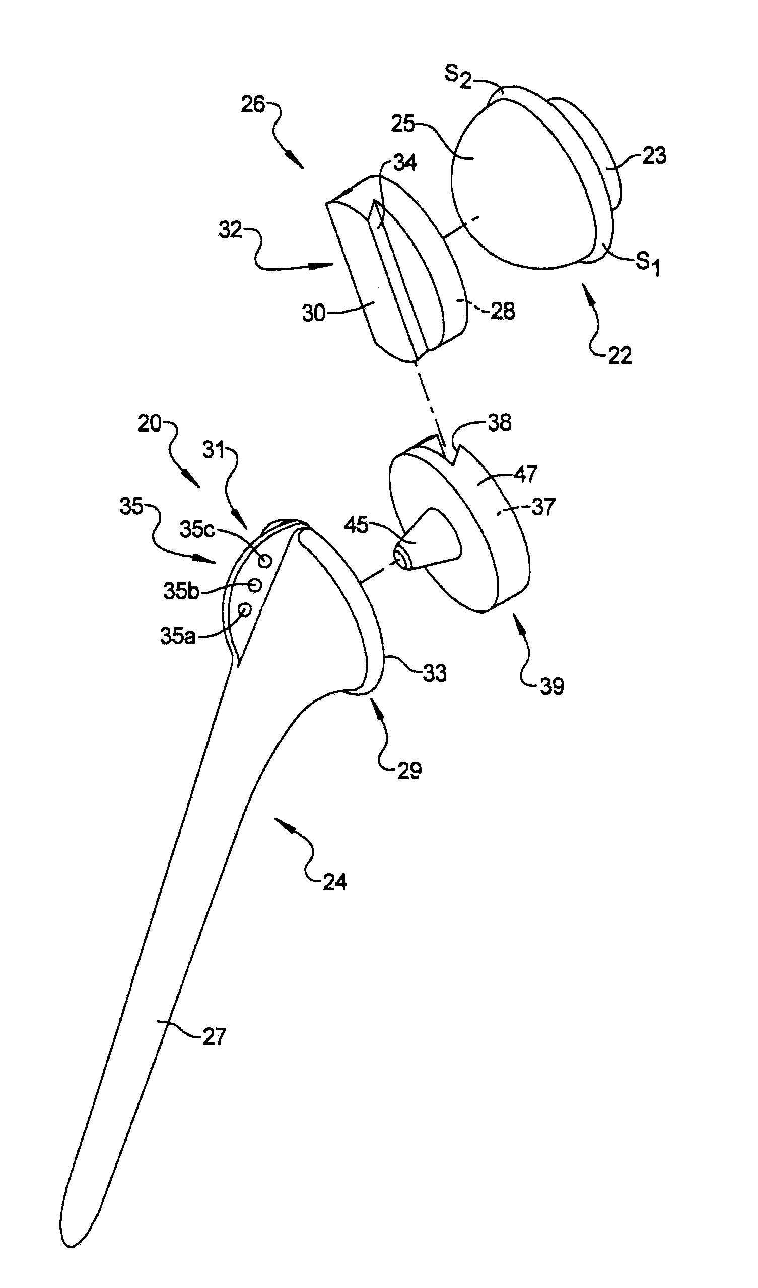
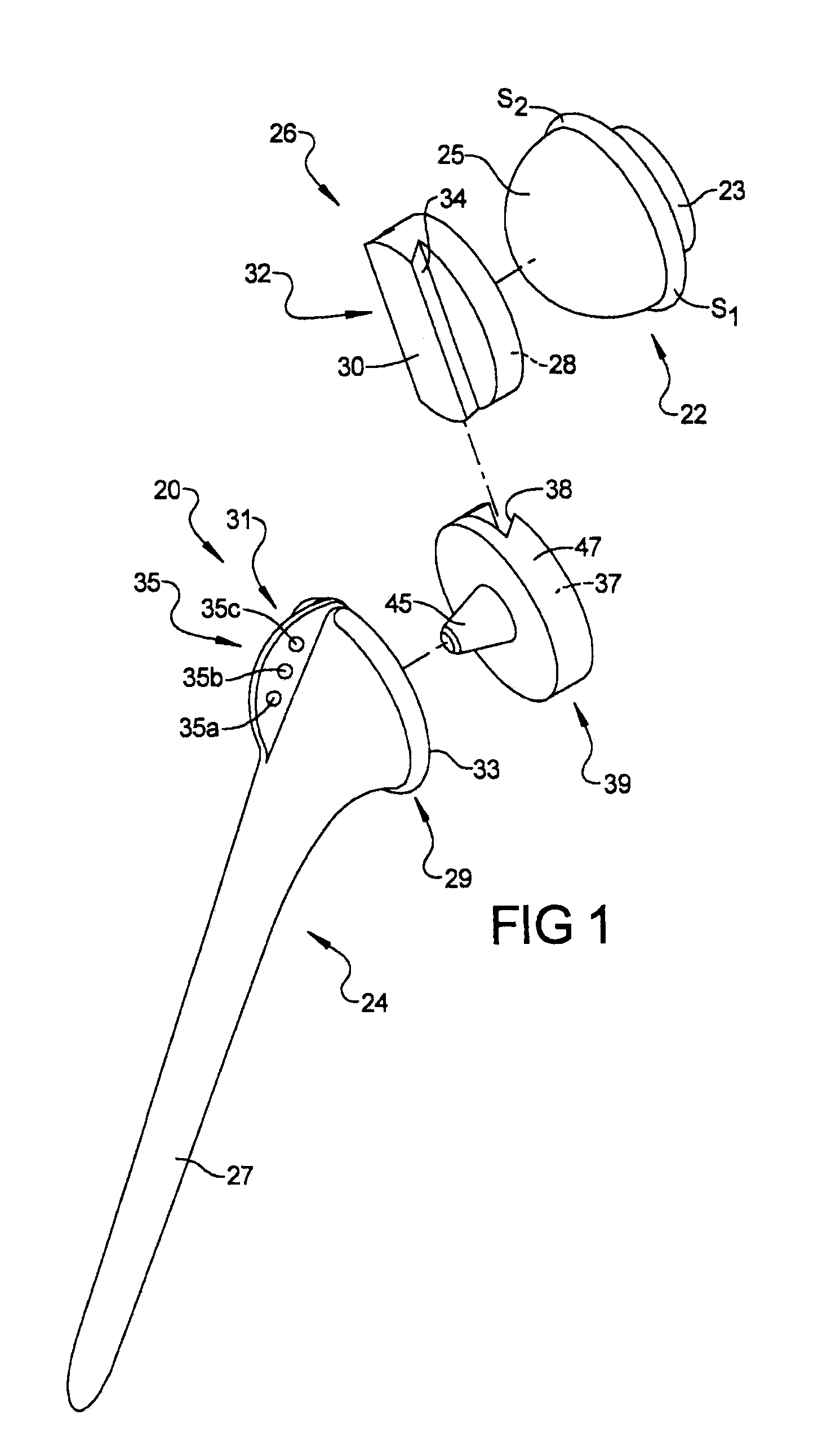
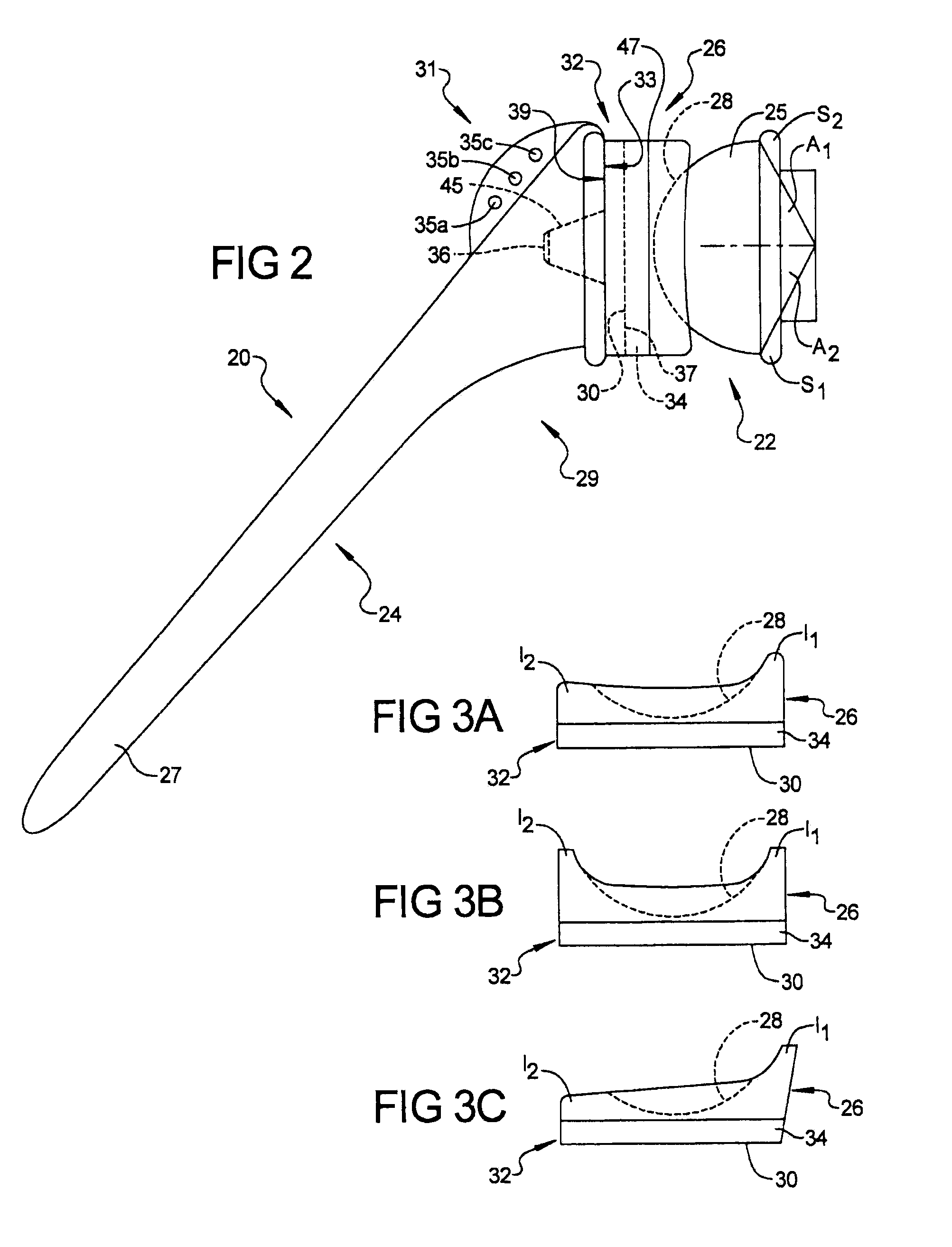
[0025]The following description is merely exemplary in nature and is not intended to limit the present teachings, application, or uses. It should be understood that throughout the drawings, corresponding reference numerals indicate like or corresponding parts and features. Although the following description is related generally to a humeral implant having a floating bearing for use in an anatomy to restore function to damaged tissue, such as in the case of shoulder joint, it will be understood that the teachings of the implant system as described and claimed herein can be used in any appropriate surgical procedure. For example, the teachings of the implant system described and claimed herein can be applied to repair any suitable anatomical joint, such as hip joint. Therefore, it will be understood that the following discussions are not intended to limit the scope of the present teachings and claims herein.

[0026]FIG. 1 represents an exploded view of a shoulder implant 20 according to...


PUM

PropertyMeasurementUnit
forceaaaaaaaaaa
distanceaaaaaaaaaa
relative rotationaaaaaaaaaa

Abstract

A shoulder can include a fixed bearing having a generally spherical articulating surface configured to be coupled to a glenoid. The implant can also include a floating bearing member defining a first spherical bearing surface and a second planar articulating bearing surface. The implant can include a stem defining a stem planar bearing surface coupled to the second planar articulating bearing surface. The second planar articulating bearing surface can cooperate with the stem planar bearing surface to enable the floating bearing to translate relative to the stem.

Description

CROSS-REFERENCE TO RELATED APPLICATIONS[0001]This application claims the benefit of U.S. Provisional Application No. 61 / 595,852, filed on Feb. 7, 2012. The entire disclosure of the above application is incorporated herein by reference.INTRODUCTION[0002]It is not uncommon for the exterior surface of the humeral head to become damaged or defective over time. Conventionally, a variety of humeral head resurfacing implants exist for repairing humeral head surfaces. While conventional humeral head resurfacing implants are suitable for their intended uses, such implants are subject to improvement.[0003]Motion of a natural shoulder is kinematically complex. During a relatively broad range of flexion and extension, the articular or bearing surfaces of a natural shoulder experience rotation, medial and lateral angulation, translation, rollback and sliding. Shoulder joint implants, in combination with ligaments and muscles, attempt to duplicate this natural shoulder motion, as well as absorb a...

Claims


Application Information

Patent Timeline
Patent Type & Authority Applications(United States)
IPC IPC(8): A61F2/40
CPCA61B17/842A61F2002/4085A61F2002/30398A61F2002/30604A61F2/40A61F2/4014A61F2/4081A61F2002/30331A61F2002/30332A61F2002/30387A61F2002/30518A61F2002/30594A61F2002/30649A61F2002/30662A61F2002/30884A61F2002/4022A61F2002/30064Y10T29/49636A61F2/34A61F2002/3052A61F2002/3483
Inventor WINSLOW, NATHAN A.MCDANIEL, JOHN M.
Owner BIOMET MFG CORP
Why Eureka
Try Eureka