Microelectronic substrate or element having conductive pads and metal posts joined thereto using bond layer

a technology of microelectronic substrates and metal posts, which is applied in the direction of semiconductor devices, electrical equipment, semiconductor/solid-state device details, etc., can solve the problems of difficult to achieve metal columns with uniform height, size and shape, and become more difficult to package semiconductor chips in a flip-chip manner

Inactive Publication Date: 2010-02-25
INVENSAS CORP
View PDF100 Cites 139 Cited by
  • Summary
  • Abstract
  • Description
  • Claims
  • Application Information

AI Technical Summary

Benefits of technology

The patent text describes a technology where a layer of material is used to join electrically conductive interconnections between posts and contacts of an external component. The technology is designed to prevent the layer of material from melting at a lower temperature than the joining process. This results in a higher melting temperature for the layer of material, which improves the reliability and performance of the technology.

Problems solved by technology

The technical problem addressed in this patent text is the difficulty of packaging semiconductor chips in a flip-chip manner due to the high density of chip contacts and the resulting reduction in the volume of solder available for joining each chip contact to the package substrate. This problem requires a minimum stand-off height between the chip and substrate to allow for compensation for differential thermal expansion between the chip and substrate. However, existing methods for forming metal columns or bumps of solder paste onto the chip or substrate are difficult to achieve with uniform height, size, and shape when the size and height of the columns or bumps are very small.

Method used


Image

  • Microelectronic substrate or element having conductive pads and metal posts joined thereto using bond layer
  • Microelectronic substrate or element having conductive pads and metal posts joined thereto using bond layer
  • Microelectronic substrate or element having conductive pads and metal posts joined thereto using bond layer

Examples


Embodiment Construction

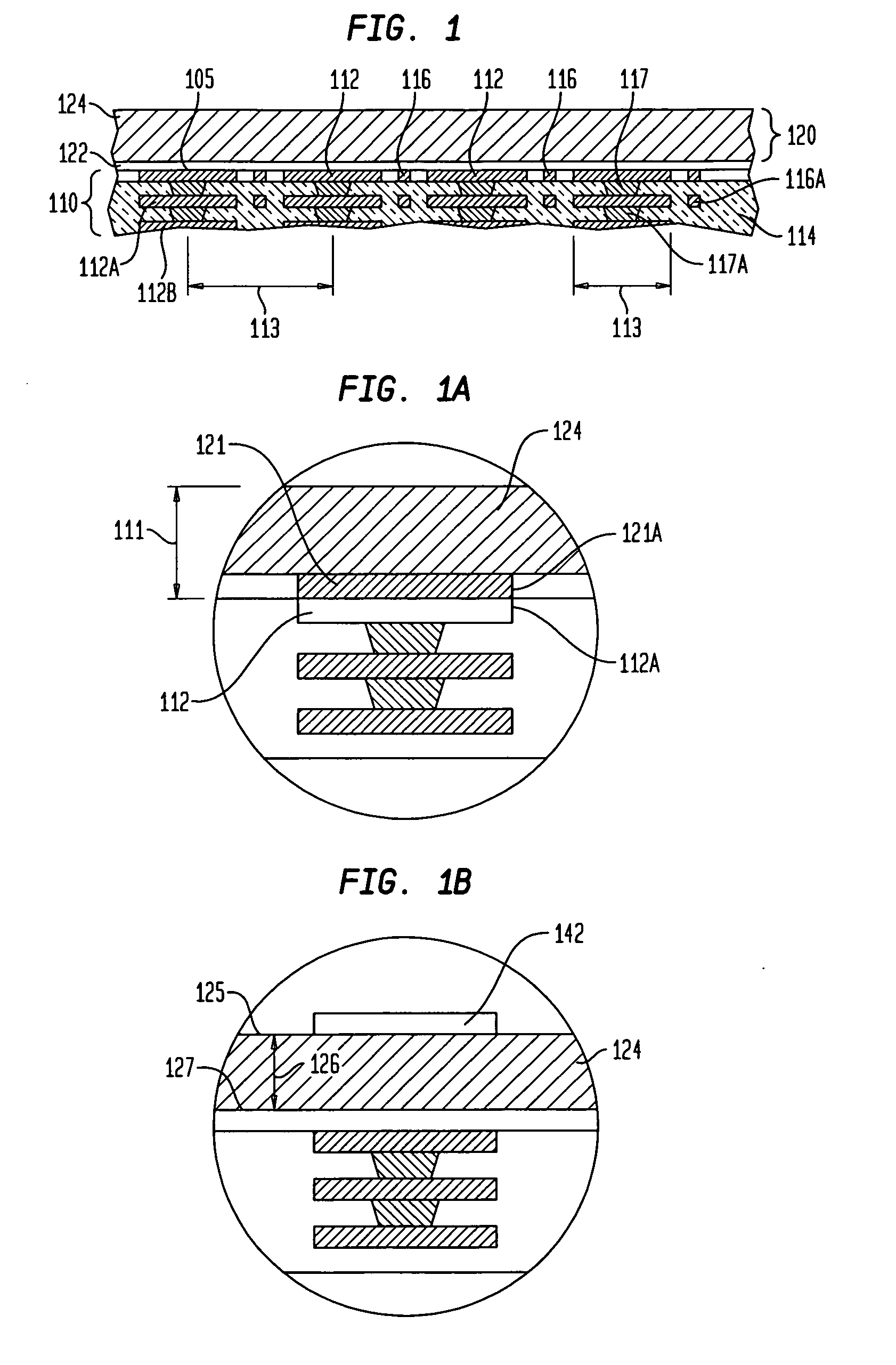
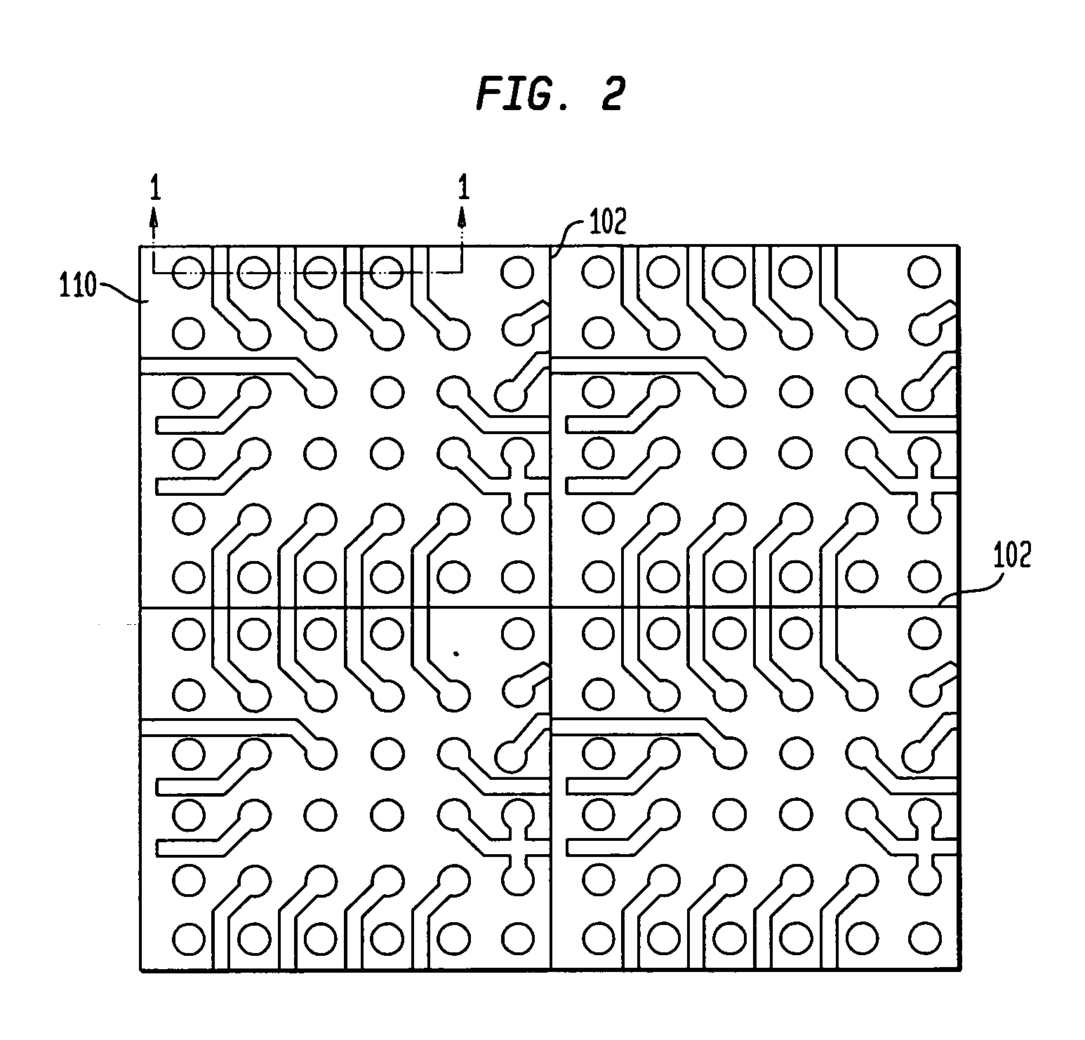
[0049]FIG. 1 is a fragmentary sectional view illustrating a stage in a method of fabricating a substrate having a copper bump interface in accordance with one embodiment herein. As seen in FIG. 1, an interconnection substrate 110, which can be fully or partially formed, is joined with a layered metal structure 120 such that a bond layer 122 of the layered metal structure contacts conductive pads 112 exposed at a major surface of a dielectric element 114. In one particular embodiment, the substrate can include a dielectric element bearing a plurality of conductive elements which can include contact, traces or both contacts and trace. The contacts can be provided as conductive pads having larger diameters than widths of the traces. Alternatively, the conductive pads can be integral with the traces and can be of approximately the same diameter or only somewhat larger than widths of the traces. Without limitation, one particular example of a substrate can be a sheet-like flexible dielec...


PUM


Abstract

An interconnection element can include a substrate, e.g., a connection substrate, element of a package, circuit panel or microelectronic substrate, e.g., semiconductor chip, the substrate having a plurality of metal conductive elements such as conductive pads, contacts, bond pads, traces, or the like exposed at the surface. A plurality of solid metal posts may overlie and project away from respective ones of the conductive elements. An intermetallic layer can be disposed between the posts and the conductive elements, such layer providing electrically conductive interconnection between the posts and the conductive elements. Bases of the posts adjacent to the intermetallic layer can be aligned with the intermetallic layer.

Description


Claims


Application Information

Patent Timeline
Owner INVENSAS CORP
Why Eureka
Try Eureka