Distortion compensator, optical receiver, distortion compensator and optical receiver controlling methods, and optical transmission system

a technology of distortion compensator and optical receiver, applied in the direction of optical transmission, electromagnetic transmission, polarisation multiplex system, etc., can solve the problems of limited compensation accuracy, waveform distortion, and restrict the increase of transmission distance and capacity of optical transmission system

Active Publication Date: 2010-02-25
FUJITSU LTD
View PDF6 Cites 35 Cited by
  • Summary
  • Abstract
  • Description
  • Claims
  • Application Information

AI Technical Summary

Benefits of technology

[0009]According to embodiment(s) of the present invention, there are further provided a distortion compensator controlling method and an optical receiver controlling method, each including a distortion compensating operation having an operation compensating for linear waveform distortion exerted on an optical signal and an operation compensating for nonlinear...

Problems solved by technology

However, waveform distortion exerted on light in an optical fiber is one of factors that restricts the increases in transmission dist...

Method used


Image

  • Distortion compensator, optical receiver, distortion compensator and optical receiver controlling methods, and optical transmission system
  • Distortion compensator, optical receiver, distortion compensator and optical receiver controlling methods, and optical transmission system
  • Distortion compensator, optical receiver, distortion compensator and optical receiver controlling methods, and optical transmission system

Examples


Embodiment Construction

[0038]Reference will now be made in detail to the embodiments, examples of which are illustrated in the accompanying drawings, wherein like reference numerals refer to the like elements throughout. The embodiments are described below to explain the present invention by referring to the figures.

[0039]Next, preferred embodiments of the present invention will be described with reference to the accompanying drawings.

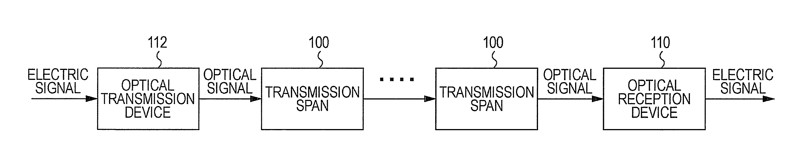
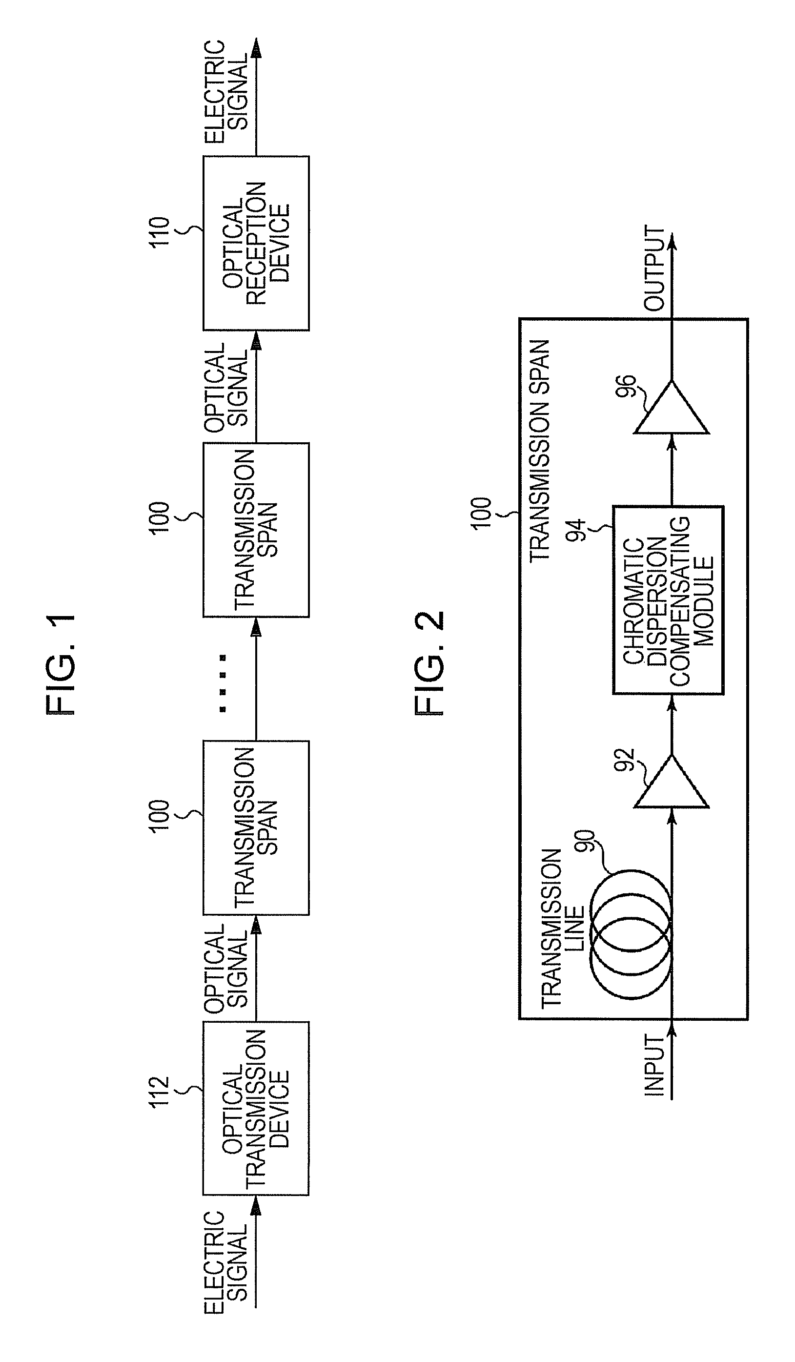
[0040]FIG. 1 is a block diagram illustrating an optical transmission system. In the optical transmission system illustrated in FIG. 1, an optical transmission device 112 converts an electric signal to an optical signal and outputs the converted optical signal to an optical transmission line. The optical transmission line has a plurality of cascade-connected transmission spans 100. The transmission span 100 at the first stage receives the optical signal sent from the optical transmission device 112. The optical signal is propagated through a plurality of stages of transmissio...


PUM


Abstract

A distortion compensator, an optical receiver and a transmission system including an operation selectively compensating for linear waveform distortion exerted on an optical signal via a plurality of distortion compensators and compensating for nonlinear waveform distortion exerted on the optical signal using nonlinear distortion compensators.

Description

CROSS-REFERENCE TO RELATED APPLICATIONS[0001]This application is based upon and claims the benefit of priority of the prior Japanese Patent Application No. 2008-211196, filed on Aug. 19, 2008, the entire contents of which are incorporated herein by reference.BACKGROUND[0002]1. Field[0003]The present invention relates to a distortion compensator, an optical receiver, distortion compensator and optical receiver controlling methods and an optical transmission system. More specifically, the present invention includes a technique of compensating for waveform distortion generated in an optical transmission line and a device implementing same.[0004]2. Description of the Related Art[0005]In communication networks, optical communication using an optical fiber as an optical transmission line is being frequently used. In order to cope with a recently promoted increase in volume of information flowing through a network, increases in distance and capacity of an optical transmission system used a...

Claims


Application Information

Patent Timeline
IPC IPC(8): H04B10/00H04B10/06H04B10/04H04B10/2507H04B10/07H04B10/2513H04B10/255H04B10/2557H04B10/556H04B10/564H04B10/58H04B10/60
CPCH03F3/08H04B10/25133H04J14/06H04B2210/252H04B1/12H04B10/697
Inventor TANIMURA, TAKAHITOHOSHIDA, TAKESHINAKASHIMA, HISAOODA, SHOICHIRO
Owner FUJITSU LTD
Why Eureka
Try Eureka