
Image forming apparatus

Inactive Publication Date: 2010-02-25
CANON KK
View PDF4 Cites 6 Cited by
  • Summary
  • Abstract
  • Description
  • Claims
  • Application Information

AI Technical Summary

Benefits of technology

[0016]The present invention is directed to an image forming apparatus which simplifies a drive mechanism of a first rotatable cleaning member which cleans a first rotatable charging member, and which can suitably clean a second rotatable charging member by a second rotatable cleaning member over a long duration.

Problems solved by technology

If the toner and external additive accumulate on the surface of the charging roller by repetition of image formation, a situation may arise where the charging step cannot be suitably performed.
More specifically, if such a situation is left as is, a life of the charging apparatus cannot be extended.
However, for the apparatus discussed in Japanese Patent Application Laid-Open No. 8-95350, deformation of a fiber portion of the rotating brush tends to increase during repeated image formation.
Further, because the fiber portion deformation is not uniform in a longitudinal direction of the rotating brush, uneven contact occurs between the rotating brush and the charging roller in the longitudinal direction.
This phenomenon is significant when a fiber length of the rotating brush is long, and cannot be ignored.
As a result, the rotating brush can no longer suitably clean the charging roller and causes cleaning defects.
However, even if this method is employed, the above-described problem still cannot be resolved.
Thus, the “relationship between the peripheral speed of the rotating brush and the peripheral speed of the charging roller” which is predetermined so that the cleaning performance by the rotating brush is suitable breaks down, and the cleaning defects may occur.

Method used


Image

  • Image forming apparatus
  • Image forming apparatus
  • Image forming apparatus

Examples


Embodiment Construction

[0027]Various exemplary embodiments, features, and aspects of the invention will be described in detail below with reference to the drawings.

[0028]A first exemplary embodiment according to the present invention will be described in detail.

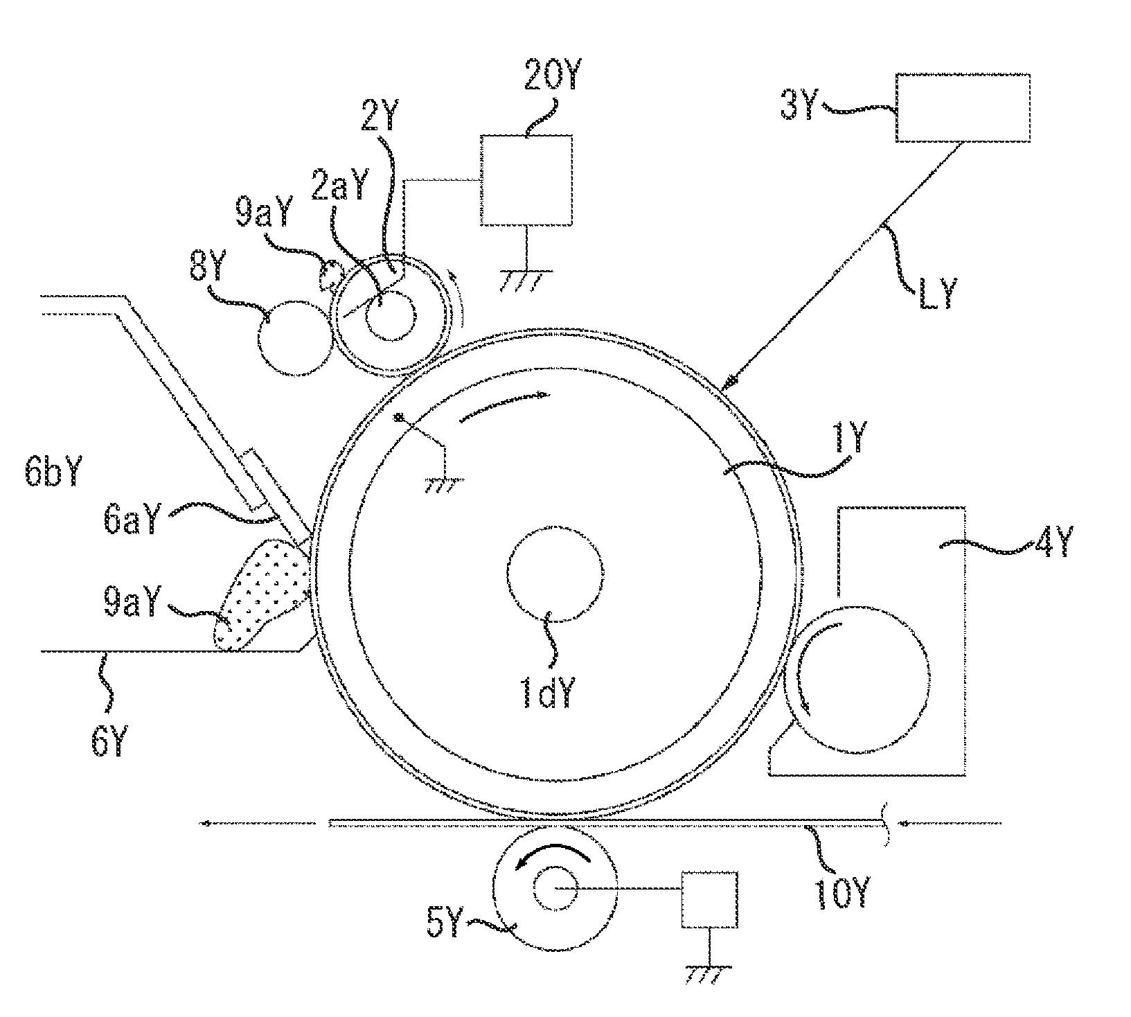
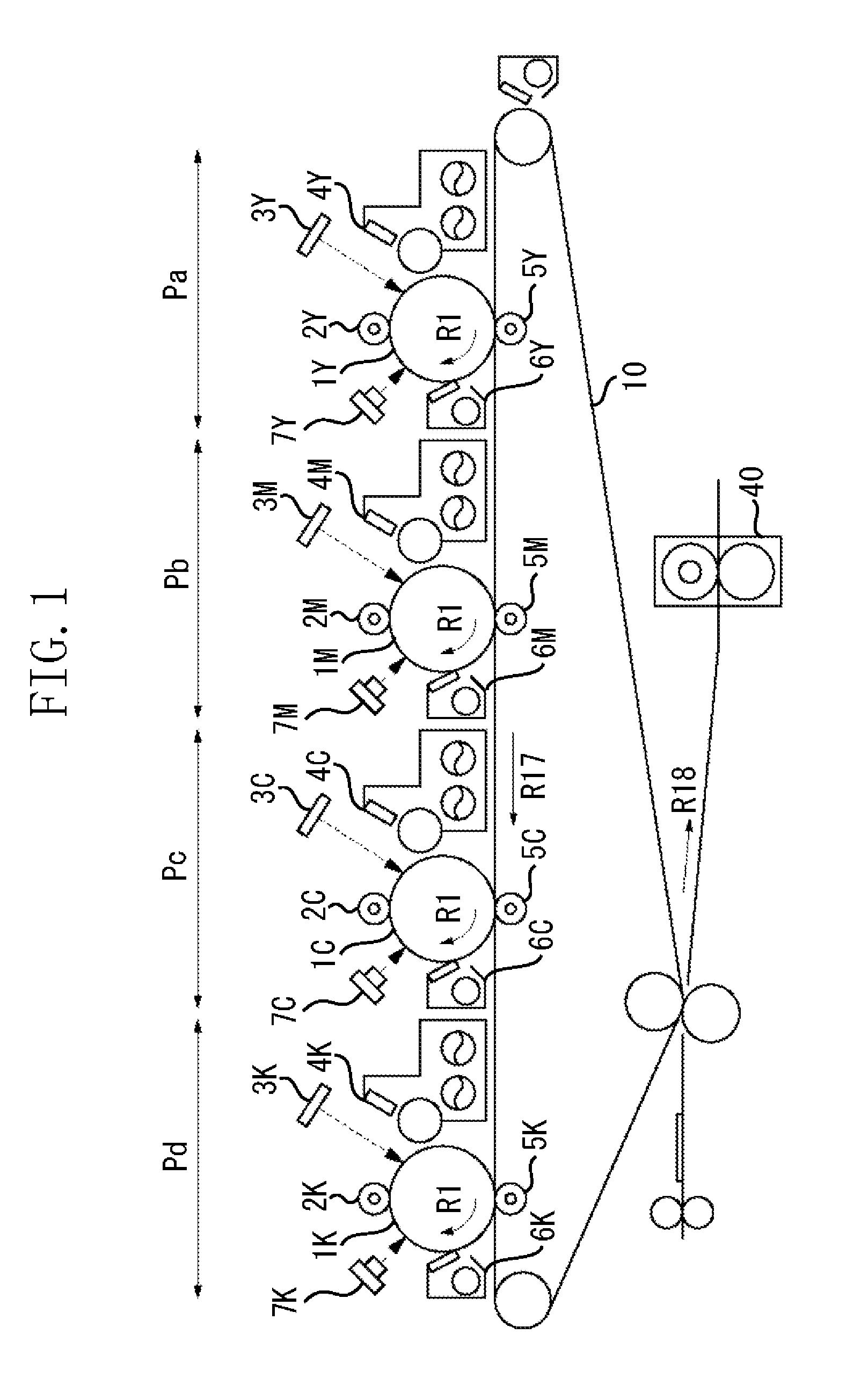
[0029]A schematic configuration of an image forming apparatus employing an electrophotographic method illustrated in FIG. 1 will be described. FIG. 1 is a schematic cross-sectional view of the image forming apparatus.

[0030]The image forming apparatus of the present exemplary embodiment is a tandem type full-color image forming apparatus having four drum type photosensitive members as an image carrier.

[0031]In the image forming apparatus, four image forming portions Pa, Pb, Pc, and Pd are arranged. The image forming portions Pa, Pb, Pc, and Pd respectively form a toner image in colors of yellow, magenta, cyan, and black.

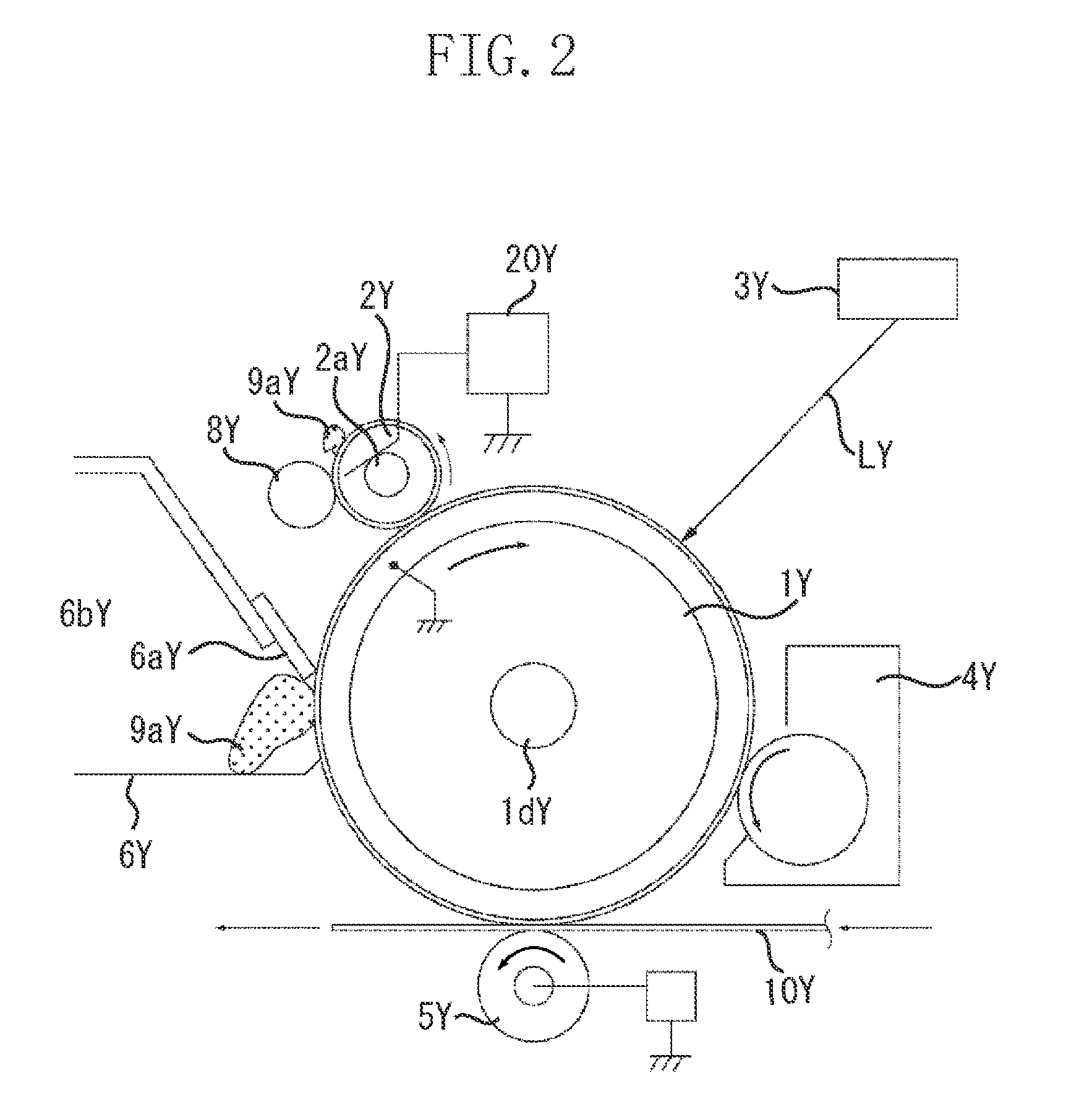
[0032]Each of the image forming portions Pa, Pb, and Pc has roughly the same configuration. The image forming portion Pa will be de...


PUM


Abstract

An image forming apparatus which includes a first image forming portion including a first photosensitive member, a first charging member for electrically charging the first photosensitive member to form an image thereon, and a first cleaning brush for cleaning the first charging member, a second image forming portion including a second photosensitive member, a second charging member for electrically charging the second photosensitive member to form an image thereon, and a second cleaning brush which has a longer brush length than that of the first cleaning brush for cleaning the second charging member, a driven mechanism for causing the first cleaning brush to be rotatably driven by the first charging member which is rotatably driven along with rotation of the first photosensitive member, and a drive coupling mechanism configured to drivably couple the second charging member and the second cleaning brush to transmit a driving force from the second charging member which is rotatably driven along with the rotation of the first photosensitive member to the second cleaning brush.

Description

BACKGROUND OF THE INVENTION[0001]1. Field of the Invention[0002]The present invention relates to an image forming apparatus using an electrophotographic method, and particularly relates to an image forming apparatus such as a copying machine, a printer, a facsimile machine and the like.[0003]2. Description of the Related Art[0004]Conventionally, an electrophotographic process used in an electrophotographic image forming apparatus includes a charging step for uniformly charging a photosensitive member.[0005]In a charging apparatus which performs the charging step, as a rotatable charging member, for example, a charging roller is in contact with the photosensitive member, and is rotatably driven by the photosensitive member. By applying a charging bias on the charging roller, a surface of the photosensitive member can be uniformly charged.[0006]Since the charging roller is charged by contacting the photosensitive member on which a toner image is formed, a slight amount of a toner or a...

Claims


Application Information

Patent Timeline
IPC IPC(8): G03G21/00
CPCG03G15/0233G03G2221/1618G03G2221/1657G03G15/0194G03G21/169G03G21/1647G03G21/1661G03G2221/1693
Inventor IMAIZUMI, KEI
Owner CANON KK
Learn More