Paper holder device
a technology of holder and blade, which is applied in the field of paper holder devices, can solve the problems of complicated oscillating mechanism of movable blade, and achieve the effects of reducing external size, promoting simplification of driving mechanism, and reducing cos
- Summary
- Abstract
- Description
- Claims
- Application Information
AI Technical Summary
Benefits of technology
Problems solved by technology
Method used
Image
Examples
first embodiment
I: First Embodiment
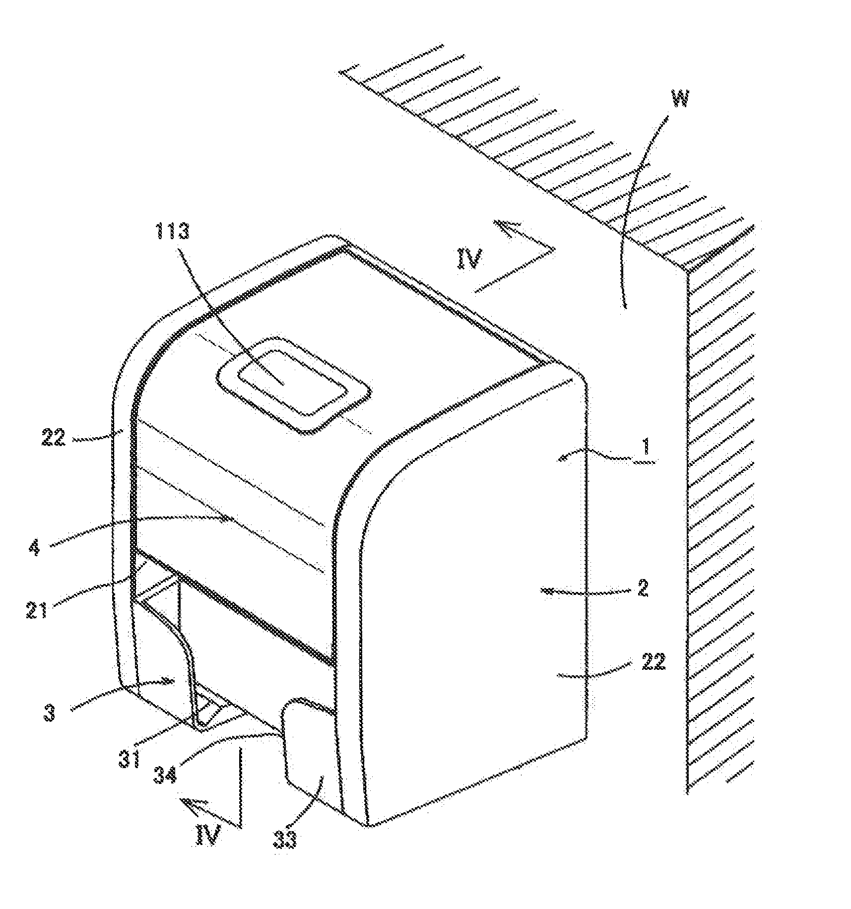
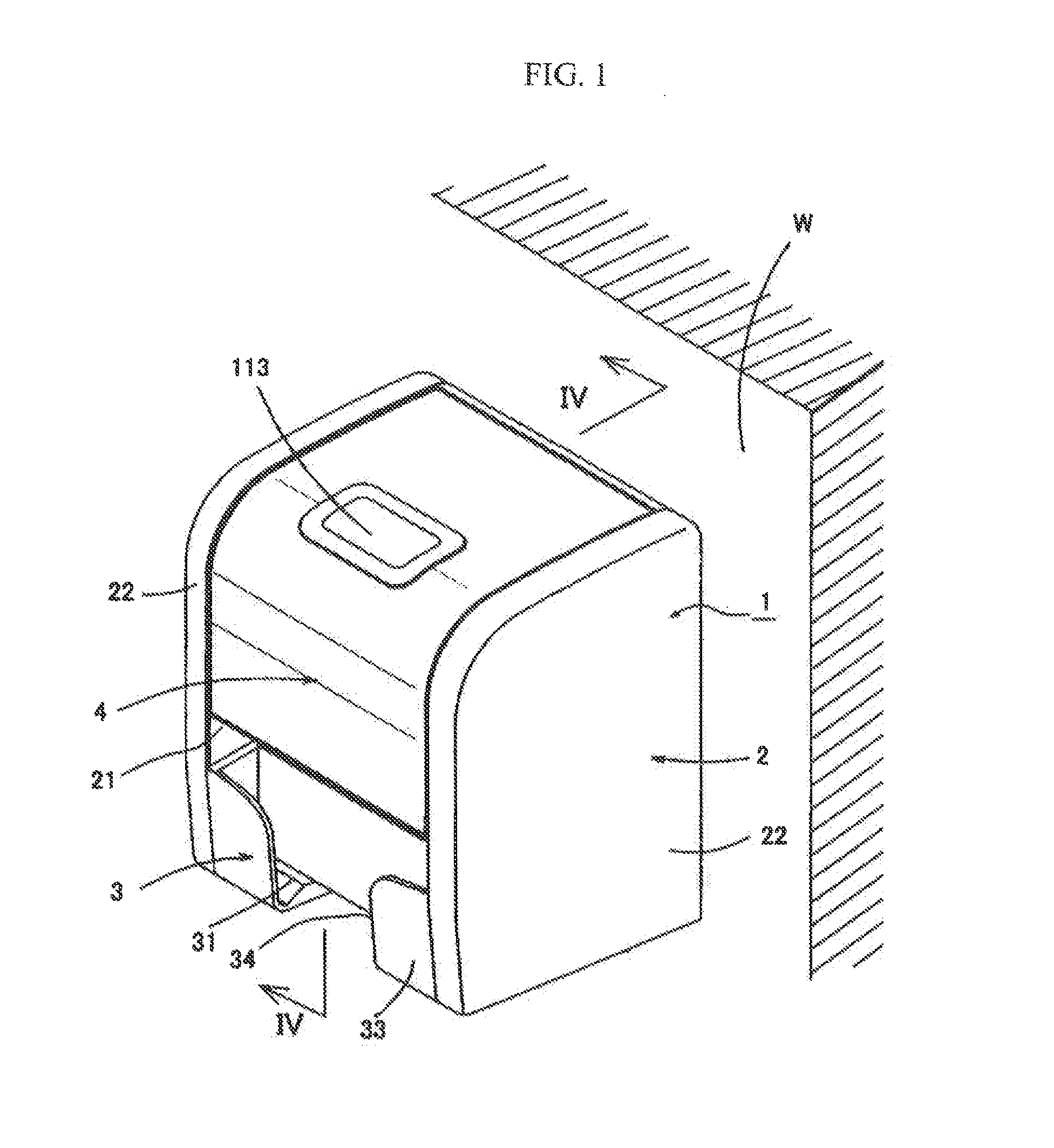
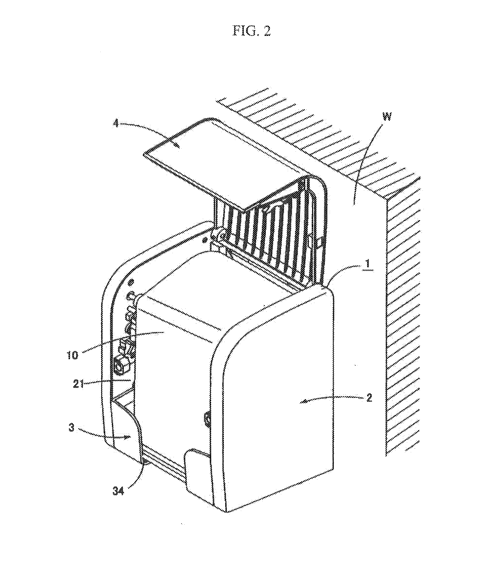
[0056]FIG. 1 to FIG. 4 show a paper holder device 1 according to a first embodiment of the present invention. The paper holder device 1, which is attached, for example, to a vertical wall W of a toilet, holds therein a paper roll 10 made by rolling toilet paper, feeds a predetermined length of paper 10a from the paper roll 10 in response to a request from a user, folds the paper 10a in a zigzag fashion, and cuts the folded paper 10a at a position close to the paper roll 10 to make it usable, and is configured to perform the series of operations from feeding to cutting of the paper 10a automatically. The automation saves the user the time and effort to pull, fold and tear the paper 10a with his or her hands. This is favorable especially to elderly people.
[0057]The paper holder device 1, which performs the series of operations automatically, includes a holder main body 2, which is described below, a paper receiving part 3 disposed in a lower part of the holder main ...
second embodiment
II: Second Embodiment
[0112]FIG. 22 to FIG. 24 show the paper holder device 1 according to a second embodiment of the present invention.
[0113]The paper holder device 1, which is slightly different in appearance (for example, the shape of the paper receiving part 3) from the paper holder device according to the first embodiment but is the same in basic configuration as the paper holder device according to the first embodiment, includes a holder main body 2, a paper receiving part 3 located in a lower part of the holder main body 2, and an access cover 4 for opening and closing a part of the holder main body 2 from one side to top as needed, and the paper supporting mechanism 5, the paper feeding mechanism 6, the paper cutting mechanism 7 and the paper folding mechanism 8 are disposed in the inner chamber 20 of the holder main body 2.
[0114]Because the configuration and function of the paper supporting mechanism 5, the paper feeding mechanism 6, the paper cutting mechanism 7 and the pap...
third embodiment
III: Third Embodiment
[0127]FIG. 25 to FIG. 28 show the paper holder device 1 according to a third embodiment of the present invention.
[0128]The paper holder device 1, which is slightly different in appearance from the paper holder device according to the first embodiment as is the case with paper holder device 1 according to the second embodiment but is the same in basic configuration as the paper holder device according to the first embodiment, includes a holder main body 2, a paper receiving part 3 located in a lower part of the holder main body 2, and an access cover 4 for opening and closing a part of the holder main body 2 from one side to top as needed, and the paper supporting mechanism 5, the paper feeding mechanism 6, the paper cutting mechanism 7 and the paper folding mechanism 8 are disposed in the inner chamber 20 of the holder main body 2.
[0129]Because the configuration and function of the paper supporting mechanism 5, the paper feeding mechanism 6, the paper cutting me...
PUM
| Property | Measurement | Unit |
|---|---|---|
| size | aaaaa | aaaaa |
| distance | aaaaa | aaaaa |
| internal structure | aaaaa | aaaaa |
Abstract
Description
Claims
Application Information
 - R&D
- Intellectual Property
- Life Sciences
- Materials
- Tech Scout
- Unparalleled Data Quality
- Higher Quality Content
- 60% Fewer Hallucinations
Browse by: Latest US Patents, China's latest patents, Technical Efficacy Thesaurus, Application Domain, Technology Topic, Popular Technical Reports.
© 2025 PatSnap. All rights reserved.Legal|Privacy policy|Modern Slavery Act Transparency Statement|Sitemap|About US| Contact US: help@patsnap.com


