Tool holder using shape memory alloy and tool holding method

a tool and shape memory technology, applied in the field of tool holders, can solve the problems of increasing the rotation imbalance factor, the accumulation error of geometrical tools, and the inability to adjust the rotational imbalance factor, so as to reduce the accumulation error, the effect of reducing the rotation imbalance factor and reducing the accumulation error

Active Publication Date: 2015-11-10
KOREA INST OF MACHINERY & MATERIALS
View PDF39 Cites 12 Cited by
  • Summary
  • Abstract
  • Description
  • Claims
  • Application Information

AI Technical Summary

Benefits of technology

[0021]According to the present invention, the interior diameter size of the tool fixing hole is forcibly expanded or restored by the variation of the shape memory alloy ring inserted to the ring fixing hole of the tool mounting unit for unclamping or clamping the tool such that a number of an entire constitution element of the tool holder is reduced thereby reducing an accumulation error, and a rotation imbalance factor may be minimized through the axis symmetry structure thereby realizing a high precision operation.
[0022]Also, the exterior size of the tool holder is reduced compared with a conventional such that the tool holder is suitable to the small spindle unit and a space that does not interference to an object under the processing is surely advantage, the clamping and unclamping operation of the tool is possible through the control of the temperature difference of about 30-40 degree in the room temperature such that the tool exchange may be easily and fast performed, and the small heating device may be applied to the exchange of the tool such that the economic load is not large compared with the conventional shrink-fit method requiring the heating device of the high cost.

Problems solved by technology

However, the conventional art has the following problems.
That is, the tool holder applied with the taper collet-chuck must be installed with a separate device for applying the force in the axial direction such as a spring or the collet nut as the taper collet to the spindle unit such that the entire structure of the tool holder is complicated such that an accurate process and assembly technique are required, and a shape error of the taper collet is accumulated, and as a result, a problem that a geometrical tool set-up error is increased is caused.
Also, deformation by centrifugal force decreases a taper contact ratio under high rotational speed of the tool holder and the tool position error of the axial direction may not only be generated, but also the structure of the spindle unit is further complicated because of adding a draw bar and a press control device in the axial direction inside the spindle unit to realize an auto tool exchange device such that a vibration mode characteristic of the spindle unit may be damaged.
Secondly, in the tool holder applied with the hydraulic-chuck method, when clamping the tool by using the high pressure, as shown in FIG. 1 (b), the separate pressing system is required such that the entire system is complicated and an auxiliary cost is added.
Also, in the case using the low pressure, as shown in FIG. 1 (c), a pressure bolt 14 is rotated at one side of the tool holder to increase the pressure, and in this case, it is difficult to realize the auto tool exchange device, and the position of the pressure volt and the arrangement of the hydraulic line inside the holder do not form axis symmetry such that a structural mass imbalance factor is generated, and as a result, the rotation accuracy of the high rotational speed is decreased.
Thirdly, the tool holder applied with the shrink-fit method applies the high temperature heat to exchange the tool such that the tool holder is moved to an additional heating system for the tool exchange after the tool holder is separated from the spindle unit, and thereby the entire system is complicated and the auxiliary cost is increased.
Also, for the unclamping of the tool, when heating to the high temperature, 1-2 minutes are taken if necessary such that the time for the tool exchange is increased, and as a result, work productivity is deteriorated.

Method used


Image

  • Tool holder using shape memory alloy and tool holding method
  • Tool holder using shape memory alloy and tool holding method
  • Tool holder using shape memory alloy and tool holding method

Examples


Embodiment Construction

[0028]Hereafter, an exemplary embodiment of the present invention will be described in detail with reference to accompanying drawings.

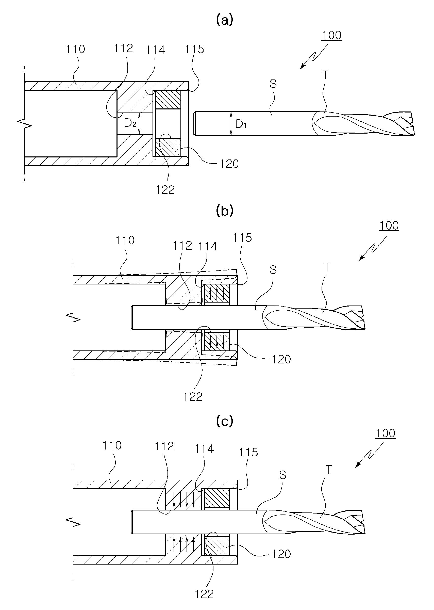
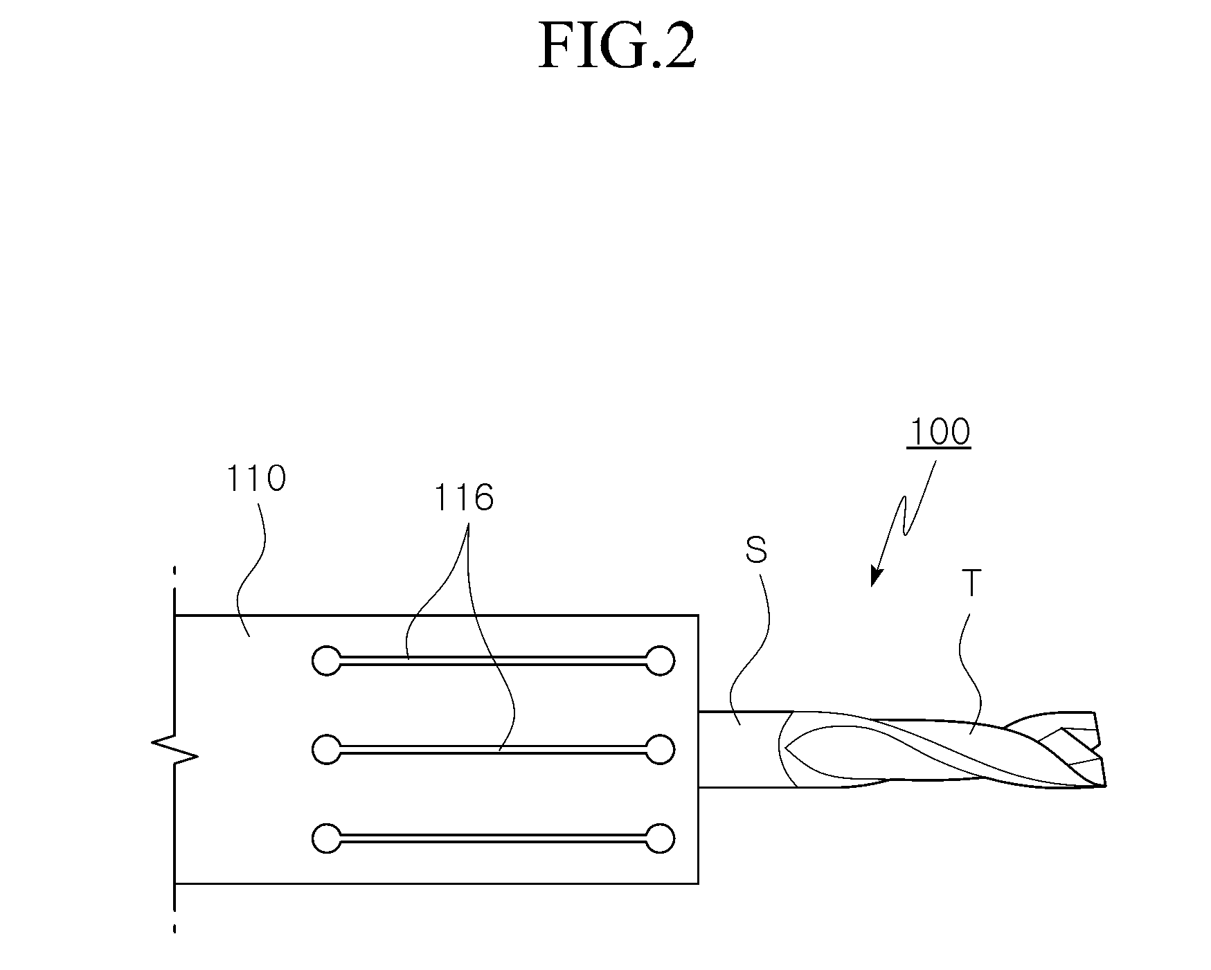
[0029]FIG. 2 is a top plan view of a tool holder using a shape memory alloy according to an exemplary embodiment of the present invention, and FIGS. 3 (a), (b), and (c) are longitudinal cross-sectional views of a state of fixing a tool by using a tool holder using a shape memory alloy according to an exemplary embodiment of the present invention.

[0030]As shown in FIG. 2 and FIGS. 3 (a), (b), and (c), a tool holder 100 according to an exemplary embodiment of the present invention includes a tool mounting unit 110 and a shape memory alloy ring 120 made of a shape memory alloy material such that the tool mounting unit 110 is elastically varied according to a state change of the shape memory alloy ring 120 for clamping or unclamping a tool (T).

[0031]The tool mounting unit 110 is integrally connected to a spindle unit that is rotatably driven by a driving ...


PUM

PropertyMeasurementUnit
finishing temperatureaaaaaaaaaa
interior diameteraaaaaaaaaa

Abstract

A tool holder holding a tool according to the present invention includes: a tool mounting unit forming and penetrating a tool fixing hole having an interior diameter that is relatively smaller than an exterior diameter of a shank unit of the tool; and at least one shape memory alloy ring inserted and arranged to a ring fixing hole formed at the tool mounting unit to have an interior diameter that is relatively larger than the tool fixing hole, wherein an interior diameter size of the tool fixing hole is forcibly changed by deformation of a shape memory alloy ring by a heating source and a cooling source provided to the shape memory alloy ring for clamping or unclamping the tool.

Description

TECHNICAL FIELD[0001]The present invention relates to a holder for holding a tool by using a shape memory alloy (SMA) and a method of holding a tool, and more particularly, to a tool holder using the shape memory alloy to reduce a number of elements of an entire device by using a shape memory alloy to realize a smaller size through a compact structure, to improve a rotation error motion under high rotational speed by minimizing a rotation imbalance factor through an axis symmetrical structure of a rotation axis, and to reduce a replacement time of unclamping and clamping of the tool, and a tool holding method thereof.BACKGROUND ART[0002]In general, a tool holder has a function of holding by clamping a tool such as a drill for mechanically processing a process object in a spindle unit of a machine tool.[0003]In this conventional tool holder, as shown in FIG. 1 (a), as a taper collet-chuck method, a tool (T) is inserted to a taper collet 10 and a force is applied in an axial direction...

Claims


Application Information

Patent Timeline
Patent Type & Authority Patents(United States)
IPC IPC(8): B23P19/04B23Q3/12B23B31/10B23B31/117B23B31/02B23P11/02
CPCB23B31/02B23B31/117B23P11/027B23B2228/16Y10T408/953B23B31/1179B23B29/04B23B29/12B23B29/06
Inventor PARK, JONG KWEONSHIN, WOO CHEOLRO, SEUNG KOOK
Owner KOREA INST OF MACHINERY & MATERIALS
Why Eureka
Try Eureka