Differential evacuation system

Active Publication Date: 2010-07-22
GIGAPHOTON
View PDF2 Cites 12 Cited by
  • Summary
  • Abstract
  • Description
  • Claims
  • Application Information

AI Technical Summary

Benefits of technology

[0022]According to the inventions of claims 1 to 5, a flow path constricting portion is provided at an intermediate position of the chamber connecting passage. Therefore, the conductance of the chamber connecting passage can be reduced. Because the chamber connecting passage has a configuration in which portions that are at opposite sides, respectively, of the flow path constricting portion are increased in inner diameter, it is possible to sufficiently ensure an optical path diverging in opposite directions away from each other from the point of convergence of light passing through the chamber connecting passage by making the light convergence point coincident with the flow path constricting portion. Further, because evacuation is performed at an optimal position in the chamber connecting passage, it is possible to perform even more effective evacuation by the vacuum pumps.
[0023]According to the invention of claim 2, the vacuum pumps are attached to an enlarged-diameter part provided at an intermediate position of the chamber connecting passage. Therefore, it is possible to easily install a plurality of vacuum pumps and hence possible to increase the differential pressure between the light generation chamber and the illumination optical chamber.
[0024]According to the invention of claim 3, the vacuum pumps can be installed so as not to project outward, which allows a reduction in the external size of the differential evacuation system. Particularly, if the vacuum pumps are installed on a side of the enlarged-diameter part in such a manner as to be circumferentially spaced from each other, it is possible to easily increase the number of vacuum pumps installed.
[0025]According to the inven

Problems solved by technology

The photolithography using such ultraviolet light, however, cannot comply with the demand for even finer semiconductor devices.
During the laser irradiation, scattering particles and ions known as debris are undesirably produced from the target.
The debris contaminates and damages a mirror that converges EUV light, causing a degra

Method used


Image

  • Differential evacuation system
  • Differential evacuation system
  • Differential evacuation system

Examples


first embodiment

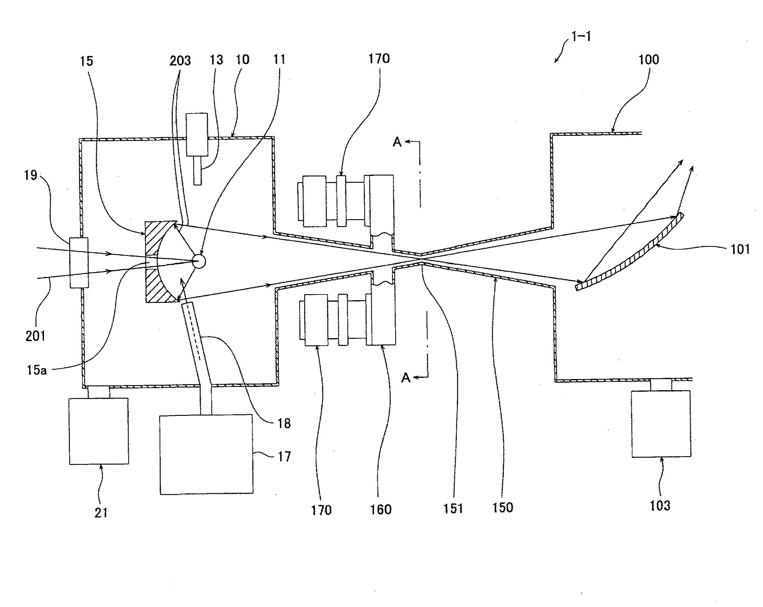
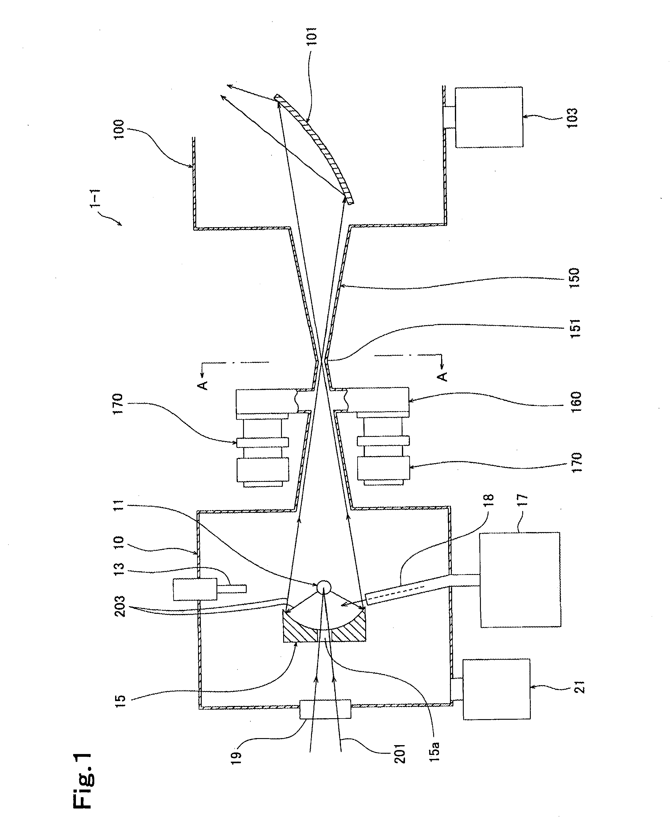
[0034]FIG. 1 is a schematic view showing the arrangement of a main part of a differential evacuation system 1-1 according to the present invention. As shown in the figure, the differential evacuation system 1-1 has a light generation chamber 10 accommodating a plasma 11 serving as a light source that generates (emits) EUV light, an illumination optical chamber 100 in which optical processing (e.g. exposure processing for semiconductor manufacture) is performed by using EUV light generated in the light generation chamber 10, and a chamber connecting passage 150 serving as a light passage that connects together the light generation chamber 10 and the illumination optical chamber 100 to guide light generated in the light generation chamber 10 into the illumination optical chamber 100.

[0035]The light generation chamber 10 has a nozzle (target material supply means) 13 that supplies a target material (e.g. xenon (Xe) gas, droplet, cluster, etc., tin (Sn) droplet, or lithium (Li) droplet)...

third embodiment

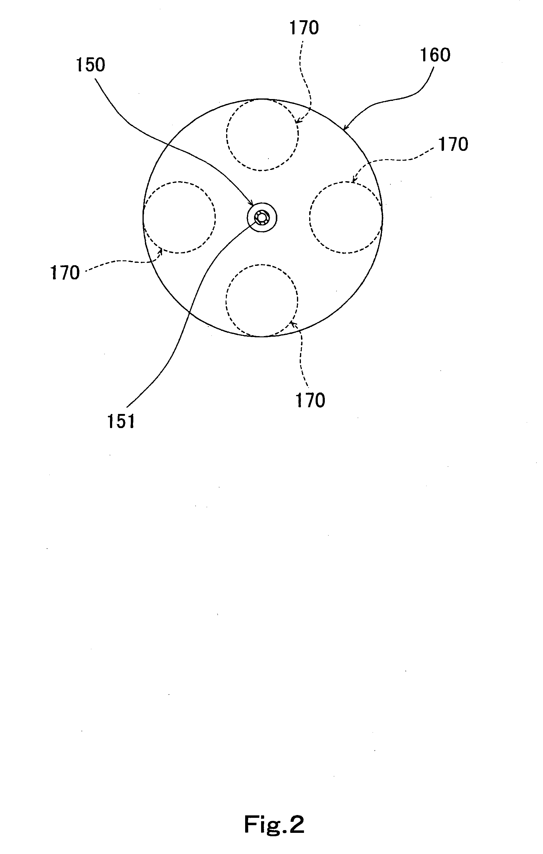
[0047]FIG. 4 is a schematic view showing the arrangement of a main part of a differential evacuation system 1-3 according to the present invention. The differential evacuation system 1-3 shown in FIG. 4 differs from the foregoing differential evacuation system 1-1 in that the position of the enlarged-diameter part 160 installed in the chamber connecting passage 150 is near the flow path constricting portion 151 of the chamber connecting passage 150 and closer to the illumination optical chamber 100 than the flow path constricting portion 151, and in that two superconducting magnets 23 are used to prevent ions and other debris from reaching the converging mirror 15 instead of blowing a buffer gas onto the surface of the converging mirror 15, thereby reducing the degradation of the reflectance of the converging mirror 15. In this embodiment, a magnetic field is generated in a direction perpendicular to the optical axis of the converging mirror 15. Ion debris is moved in the magnetic f...


PUM


Abstract

[Technical Problem] To provide a differential evacuation system capable of easily maintaining, at a low cost, a large differential pressure between a light generation chamber and an illumination optical chamber in which optical processing, e.g. exposure, is performed by using extreme ultraviolet (EUV) light generated in the light generation chamber, and yet capable of sufficiently ensuring a desired optical path.
[Solution to Problem] The differential evacuation system has a light generation chamber 10 that generates EUV light, an illumination optical chamber 100 in which optical processing is performed by using the EUV light generated in the light generation chamber 10, and a chamber connecting passage 150 that connects together the light generation chamber 10 and the illumination optical chamber 100 to guide the EUV light generated in the light generation chamber 10 into the illumination optical chamber 100. The chamber connecting passage 150 has a flow path constricting portion 151 and is increased in inner diameter in a conical tube shape at portions thereof that are at opposite sides, respectively, of the flow path constricting portion 151. An enlarged-diameter part 160 is provided at a position of the chamber connecting passage 150 that is closer to the light generation chamber 10, which is the higher in pressure of the two chambers 10 and 100, than the flow path constricting portion 151, and vacuum pumps 170 are attached to the enlarged-diameter part 160.

Description

TECHNICAL FIELD[0001]The present invention relates to a differential evacuation system suitable for use in the manufacture of semiconductor wafers or the like using a photolithography technique.BACKGROUND ART[0002]Conventionally, semiconductor devices such as semiconductor memories are manufactured by a method using a reduced projection exposure apparatus in which a circuit pattern drawn on a reticle or a mask is projected onto a wafer or the like through a projection optical system to transfer the circuit pattern to the wafer. The smallest size (resolution) of a circuit pattern that can be transferred by the reduced projection exposure apparatus is proportional to the wavelength of light used for exposure. Therefore, the shorter the wavelength, the higher the resolution. Accordingly, the wavelength of light used for exposure is becoming shorter and shorter with the increasing demand for finer semiconductor devices. Thus, progressively shorter wavelengths of ultraviolet light have b...

Claims


Application Information

Patent Timeline
IPC IPC(8): G21K5/02
CPCG03F7/70033G03F7/70808H05G2/008H05G2/003G03F7/70841
Inventor SOMEYA, HIROSHIWATANABE, YUKIO
Owner GIGAPHOTON
Why Eureka
Try Eureka