Magnetorheological damper with built-in magnetorheological valve for damping performance control

A magnetorheological damper, magnetorheological valve technology, applied in the direction of shock absorber, shock absorber, liquid shock absorber, etc., can solve the problem of increasing the effective damping gap, the failure of the magnetorheological damper, blocking the damping gap, etc. problems, to achieve the effect of wide dynamic adjustment range, enhanced yield stress, and increased damping length

Active Publication Date: 2015-10-28
EAST CHINA JIAOTONG UNIVERSITY
View PDF7 Cites 12 Cited by
  • Summary
  • Abstract
  • Description
  • Claims
  • Application Information

AI Technical Summary

Problems solved by technology

A common method is to reduce the width of the damping gap of the magnetorheological damper. However, when the magnetorheological fluid is left unused for a long time and is used again, particles are prone to precipitate and block the damping gap, resulting in the failure of the magnetorheological damper.
The second is to increase the length of the effective damping gap, but this will significantly increase the volume of the magnetorheological damper, occupy more installation and use space, and increase the manufacturing cost accordingly
[0007] Based on this, in the actual design process, it is difficult to simultaneously increase the magnetic induction intensity in the effective damping gap and increase the length of the effective damping gap

Method used


Image

  • Magnetorheological damper with built-in magnetorheological valve for damping performance control
  • Magnetorheological damper with built-in magnetorheological valve for damping performance control
  • Magnetorheological damper with built-in magnetorheological valve for damping performance control

Examples


Embodiment Construction

[0021] Below in conjunction with accompanying drawing and embodiment the present invention will be further described:

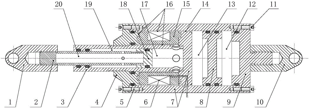
[0022] Such as figure 1 As shown, the present invention includes: left lifting lug 1, piston rod 2, piston cylinder 3, left end cover 4, screw I 5, excitation coil 6, damper cylinder 7, floating piston 8, right end cover 9, right lifting lug 10, Screw II11, compressed air chamber 12, magnetorheological fluid chamber I13, cylinder liquid flow channel 14, valve core 15, U-shaped liquid flow channel 16, magnetorheological fluid chamber II17, piston head 18, gas chamber Ⅰ19 and gas chamber Ⅱ20.

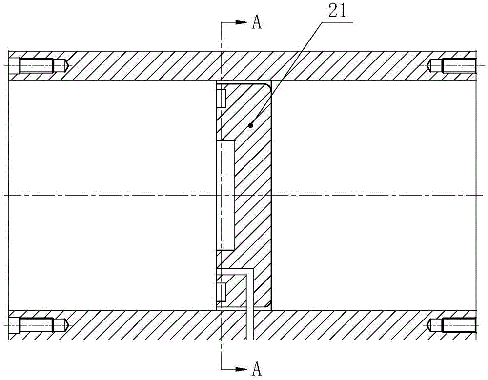
[0023] figure 2 It is a schematic diagram of the structure of the damper cylinder of the present invention, and 21 is the end cover of the damper cylinder 7 among the figures.

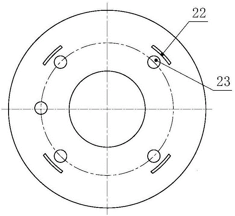
[0024] image 3 yes figure 2 The A-A sectional view of the damper cylinder block, 22 is a waist-shaped through-hole groove among the figures, and 23 is a circular groove. The end cover of...


PUM


Abstract

The invention discloses a magnetorheological damper with a built-in magnetorheological valve for damping performance control, which mainly comprises a piston rod, a piston cylinder, a damper cylinder body, a valve core, a floating piston, end covers, lifting lugs and the like. The piston rod, the damper cylinder body, the valve core, an excitation coil, cylinder liquid flow passages, and U-type liquid flow passages form the built-in magnetorheological valve. When the excitation coil is conductive, flowability of magnetorheological liquid inside effective damping gaps of the cylinder liquid flow passages and the U-type liquid flow passages is reduced due to electromagnetic effects, a pressure difference is formed between a first magnetorheological liquid accommodating cavity and a second magnetorheological liquid accommodating cavity, a damping force applied to the right end surface of the piston head changes, and the purpose that the magnetorheological valve controls the damping performance of the magnetorheological damper is realized. Due to the U-type liquid flow passages, the damping length is effectively increased, and the damping force adjustable range is increased. The magnetorheological damper is particularly suitable for being applied to a shock absorption system for a railway, a train, a bridge and the like, and has the advantages of large adjustment range, compact structure and small size.

Description

technical field [0001] The invention relates to a magnetorheological damper, in particular to a magnetorheological damper with a built-in magnetorheological valve for damping performance control. Background technique [0002] The magnetorheological damper is a new type of intelligent damping device widely used in semi-active control systems. Its characteristics of millisecond-level response speed, large control range and large damping force output make it an excellent semi-active actuator in industrial applications. At present, magnetorheological dampers have been widely used in vibration reduction and anti-seismic systems of buildings and bridges, and vibration reduction of railway rolling stock and automobile suspension systems. [0003] Magneto-rheological dampers are mainly used to control the vibration generated by system components to meet the requirements of various equipment for different working conditions and different environments. Therefore, the performance of ...

Claims


Application Information

Patent Timeline
Patent Type & Authority Applications(China)
IPC IPC(8): F16F9/53F16F9/19F16F9/34
CPCF16F9/182F16F9/19F16F9/3214F16F9/3221F16F9/3235F16F9/537
Inventor 胡国良刘丰硕
Owner EAST CHINA JIAOTONG UNIVERSITY
Why Eureka
Try Eureka