Foil bearing

a technology of oil bearings and bearings, applied in the direction of bearings, shafts and bearings, rotary bearings, etc., can solve the problems of difficult to achieve an adequate frictional damping force, and achieve the effects of wide rotational speed range, stable rotation, and large frictional damping for

Inactive Publication Date: 2006-02-14
HONDA MOTOR CO LTD
View PDF5 Cites 14 Cited by
  • Summary
  • Abstract
  • Description
  • Claims
  • Application Information

AI Technical Summary

Benefits of technology

[0005]In view of such problems of the prior art, a primary object of the present invention is to provide a foil bearing that can enable a larger frictional damping force to be generated by the foil assembly to thereby achieve a stable rotation over a wider rotation speed range.

Problems solved by technology

As shown in FIG. 5, however, a conventional corrugated bump foil F contacts radially adjoining members (a stationary mount member 3a and a top foil 5a) with its curved surfaces and thus circumferential dimensions A, B of contact areas between the bump foil F and the top foil 5a and between the bump foil F and the stationary mount member 3a are quite limited, and this makes it difficult to achieve an adequate frictional damping force.

Method used


Image

  • Foil bearing
  • Foil bearing
  • Foil bearing

Examples


Embodiment Construction

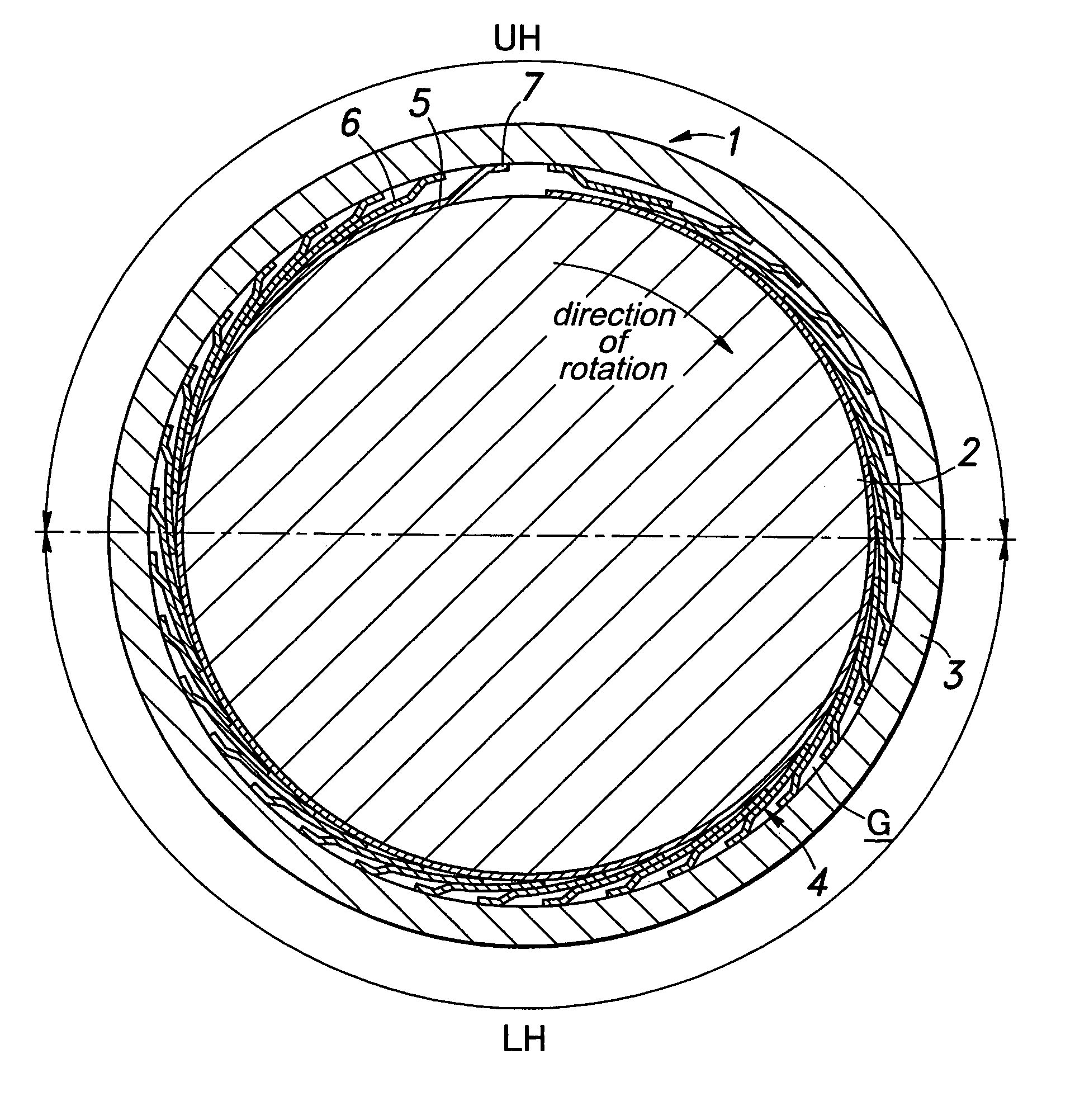
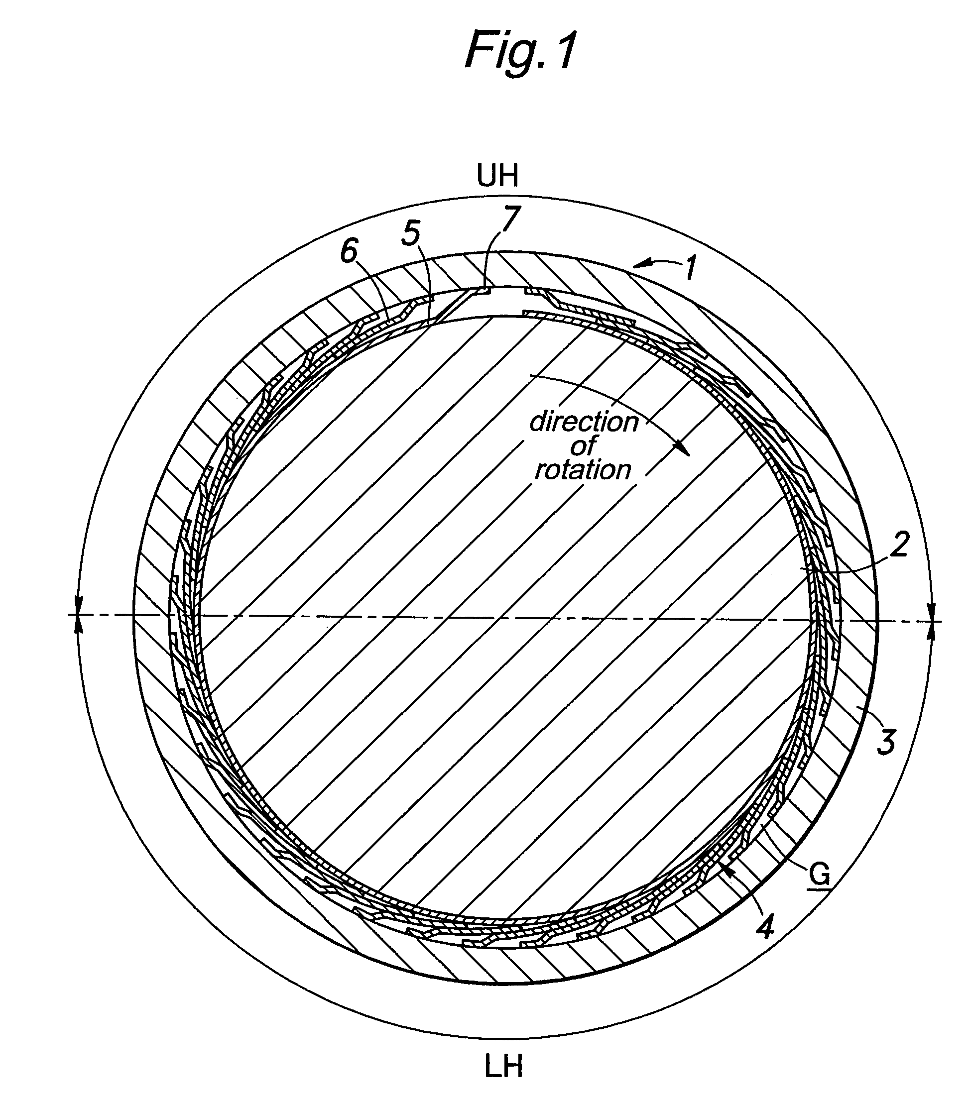
[0022]FIG. 1 shows an embodiment of a foil bearing according to the present invention. This foil bearing 1 comprises a cylindrical stationary mount member 3 which is unrotatably fixed and surrounds a journal 2 of a rotating member, and a foil assembly 4 disposed in an annular gap G defined between an outer circumferential surface of the journal 2 and an inner circumferential surface of the stationary mount member 3.

[0023]The foil assembly 4 comprises a top foil 5 placed at an inner part of the annular gap G and a plurality of spring foils 6 which are arranged successively in a circumferential direction outside the top foil 5. It should be noted that in FIG. 1, the component parts may be shown at a scale different from the actual one in order to emphasize features of the foil assembly 4.

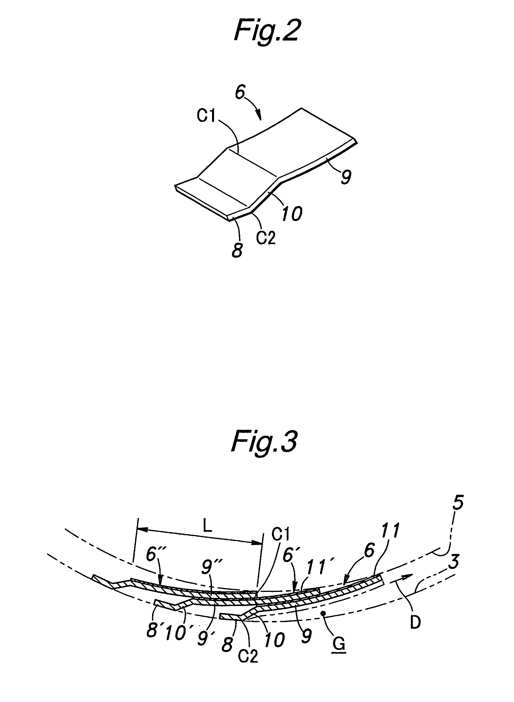
[0024]The top foil 5 consists of a sheet member made of inconel (trademark) or the like having a thickness of about 0.1 mm and is curved to extend to assume a substantially cylindrical shape so that s...


PUM


Abstract

In a foil bearing (1), a foil assembly (4) disposed between a stationary mount member (3) and a journal (2) of a rotating member comprises: a top foil (5) having one end secured to an upper portion of the stationary mount member and extending circumferentially to surround a substantially entire outer circumferential surface of the journal; and a plurality of spring foils (6) arranged in an annular gap between the top foil and the stationary mount member, wherein each of the spring foils consists of a resilient piece which is bent to have a joint portion (8) attached to the stationary mount member and a slide contact portion (9) for contacting the top foil, and wherein the spring foils are arranged in a circumferential direction such that the slide contact portions of adjoining ones of the spring foils partially overlap each other.

Description

TECHNICAL FIELD[0001]The present invention relates to a foil bearing comprising a stationary mount member surrounding a journal of a rotating member via an annular gap and a foil assembly disposed in the gap to support the journal.BACKGROUND OF THE INVENTION[0002]It is conventionally known to use a foil bearing as a bearing for a shaft (or journal) that rotates at a high speed such as at tens of thousands rpm, in which the foil bearing comprises a plurality of foils (flexible membranes) for forming a bearing surface and supports the shaft by means of pressure of a fluid dragged in between the shaft and the foils as the shaft rotates. In some of such foil bearings, a foil assembly is constituted by a cylindrical bearing sheet and a plurality of bump foils, each of which consists of a corrugated thin plate and is disposed radially outward of the cylindrical bearing sheet (see U.S. Pat. No. 4,277,113, for example).[0003]In the foil bearings of this type, it is known that a resonance ph...

Claims


Application Information

Patent Timeline
Patent Type & Authority Patents(United States)
IPC IPC(8): F16C32/06F16C17/02F16C17/12F16C33/12
CPCF16C17/024F16C27/02F16C2300/22
Inventor KATOU, DAISUKENAKATA, HIDEHIKO
Owner HONDA MOTOR CO LTD
Why Eureka
Try Eureka