Fluid damper

A fluid damper, fluid technology, applied in liquid shock absorbers, shock absorbers, shock absorbers, etc., can solve problems such as long-term continuous standby, and achieve the effect of good vibration suppression and small damping force

Inactive Publication Date: 2009-03-04
CENTRAL RESEARCH INSTITUTE OF ELECTRIC POWER INDUSTRY
View PDF1 Cites 14 Cited by
  • Summary
  • Abstract
  • Description
  • Claims
  • Application Information

AI Technical Summary

Problems solved by technology

Therefore, it is difficult to say that it is suitable for a damping device that requires a long-term standby state on the one hand, and on the other hand, needs to be able to reliably operate to exhibit specified performance in the event of a sudden earthquake, such as the anti-vibration damper of a structure.

Method used


Image

  • Fluid damper
  • Fluid damper
  • Fluid damper

Examples


Embodiment Construction

[0083] Hereinafter, the configuration of the present invention will be described in detail with reference to the preferred embodiments shown in the drawings.

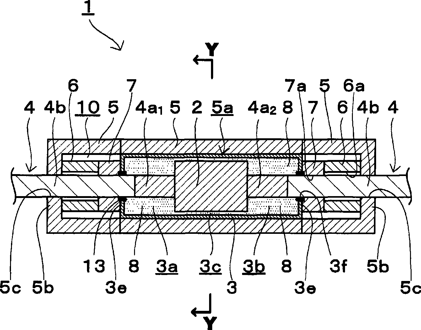
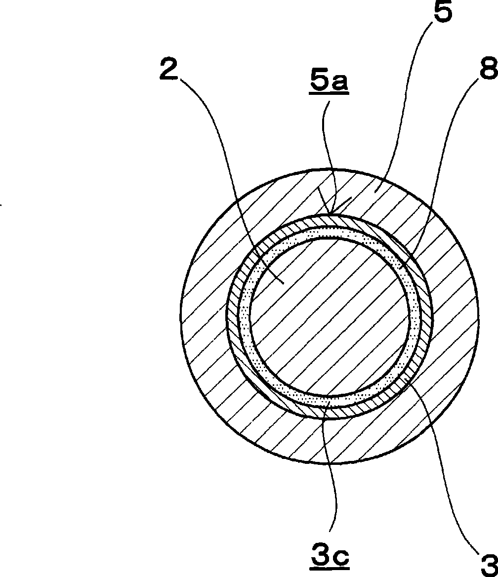
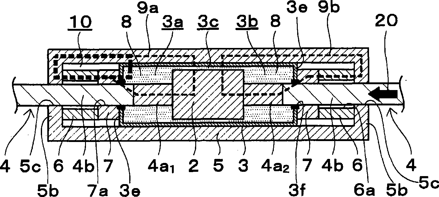
[0084] figure 1 ˜ FIG. 5 show a first embodiment of the fluid damper of the present invention. The fluid damper 1 has: a magnetic fluid 8; a magnetic piston 2; a cylinder 3 that seals the magnetic fluid 8 and accommodates the piston 2; a piston rod 4 that penetrates the cylinder 3 and supports the piston 2; A magnetic field generating device 6 outside the cylinder 3; a first yoke piece 5 disposed around the cylinder 3; and a second yoke piece 7 disposed around the piston rod 4 outside the cylinder 3.

[0085] The cylinder 3 has a cylindrical peripheral wall and end face members 3 e at both ends in the axial direction, and a hollow portion, that is, a cylinder chamber is formed by them. 3 f of through-holes through which the piston rod 4 penetrates are provided in the center part of the end surface member 3e. In additi...


PUM


Abstract

A fluid damper which is capable of operating while automatically changing the damping force according to the movement of a piston without installing a sensor detecting the displacement of the piston and a controller controlling the supply of electric power. The fluid damper, in which the damping force is automatically changed according to the movement of the piston, comprises a fluid (8) having magnetism, a piston (2) of magnetic material, a cylinder (3) sealing the fluid (8) with magnetism and storing the piston (2), a piston rod (4) passed through the cylinder (3) and supporting the piston (2), magnetic field generating device (6) installed on the outside of the cylinder (3), first yoke member (5) disposed around the cylinder (3), and second yoke member (7) disposed around the piston rod (4) and on the outside of the cylinder (3). Thereby, a magnetic circuit can be partially formed.

Description

technical field [0001] The present invention relates to a fluid damper using magnetic fluid as a working fluid. More particularly, the present invention relates to a fluid damper suitable for use as, for example, a shock absorber of a structure. Background technique [0002] As an existing fluid damper using a magnetic fluid as a working fluid, such as Figure 18 The shown device has: a cylinder 101, a piston 102, a first fluid chamber 103 and a second fluid chamber 104 divided in the cylinder 101 by the piston 102, filled in the first fluid chamber 103 and the second fluid chamber 104 The magnetic viscous fluid 105 of the piston 102, the electromagnet 108 composed of a coil in which an electric wire is wound on the groove portion 102a recessed on the outer periphery of the piston 102, and the external power supply control device 110 for supplying electric power to the electromagnet 108 through the wiring 109 , using the power supply control device 110 to supply power to th...

Claims


Application Information

Patent Timeline
Patent Type & Authority Applications(China)
IPC IPC(8): F16F9/53F16F9/20
CPCF16F9/535
Inventor 村上贵裕荒关英夫
Owner CENTRAL RESEARCH INSTITUTE OF ELECTRIC POWER INDUSTRY
Why Eureka
Try Eureka