Damper and vibration damping structure using the same

a technology of vibration damping and damping structure, which is applied in the field of dampers, can solve the problems of abnormal noise generation, increase in the cost of using such swivel fittings or the like, and impair the damping effect, so as to reduce the cost, reduce the cost, and improve the effect of damping

Inactive Publication Date: 2007-02-27
OILES CORP
View PDF17 Cites 13 Cited by
  • Summary
  • Abstract
  • Description
  • Claims
  • Application Information

AI Technical Summary

Benefits of technology

[0010]In accordance with the damper according to the first aspect, by connecting this damper to such as columns and horizontal members by means of the respective attaching plate members, the inner elongated body is relatively moved in the axial direction with respect to the outer elongated body in the relative vibration of, for instance, the lower horizontal member with respect to the upper horizontal member in a horizontal direction within the plane of the wall space owing to an earthquake or the like. In consequence, the viscous body or the viscoelastic body disposed in the gap between the inner surface of the outer elongated body and the outer surface of the inner elongated body is caused to undergo viscous shear deformation and is capable of absorbing the relative vibrational energy. Further, the damper can be simply and firmly connected to the columns, the horizontal members, or the like by means of the respective attaching plate members instead of the swivel fittings, through, for example, frictional joining using the splice plates and the like for clamping the attaching plate members at wide attaching surfaces of the attaching plate members. Therefore, it is possible to install the damper in the wall with a simple construction in the form of a diagonal brace or in parallel to the column, and it is possible to lower the cost. Moreover, abnormal noise does not occur in the shaking, and looseness in installation does not occur. Additionally, it is possible to attain low cost and obtain firm connection.
[0044]In addition, in accordance with the present invention, it is possible to provide a damper which is capable of generating a large damping force without enlarging the occupying space in the axial direction and the weight and without causing an undesirable situation such as contact between the elongated bodies, as well as a vibration damping structure using the same.

Problems solved by technology

However, the use of such swivel fittings or the like entails a rise in the cost.
Moreover, there is a possibility of abnormal noise being generated due to the sliding in swinging, and there is a possibility of impairing the damping effect due to looseness in installation.
In addition, with the cylinder-rod type damper, if the cylinder and the rod are made long in an attempt to generate a large damping force so as to efficiently damp vibrations due to an earthquake at an early period, the occupying space in the axial direction becomes large in the installation.
Moreover, a thick cylinder and a large rod are inevitably used so as not to cause deflection or the like, so that the weight becomes extremely large.

Method used


Image

  • Damper and vibration damping structure using the same
  • Damper and vibration damping structure using the same
  • Damper and vibration damping structure using the same

Examples


Embodiment Construction

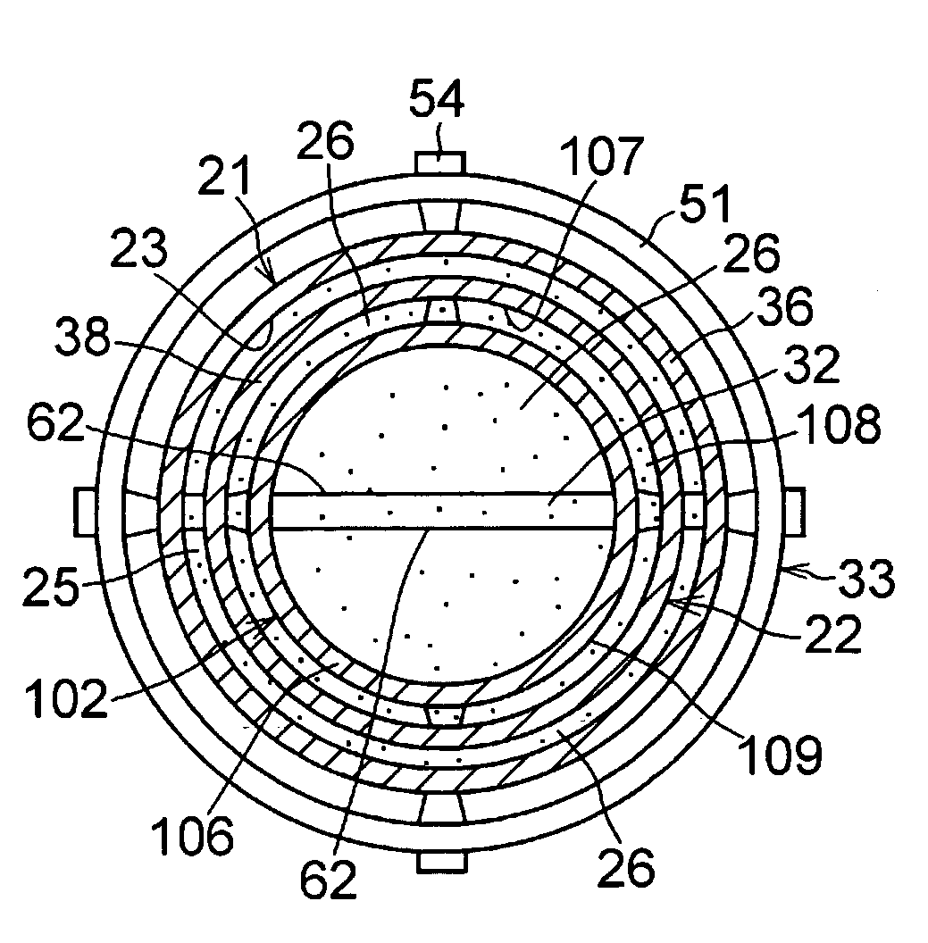
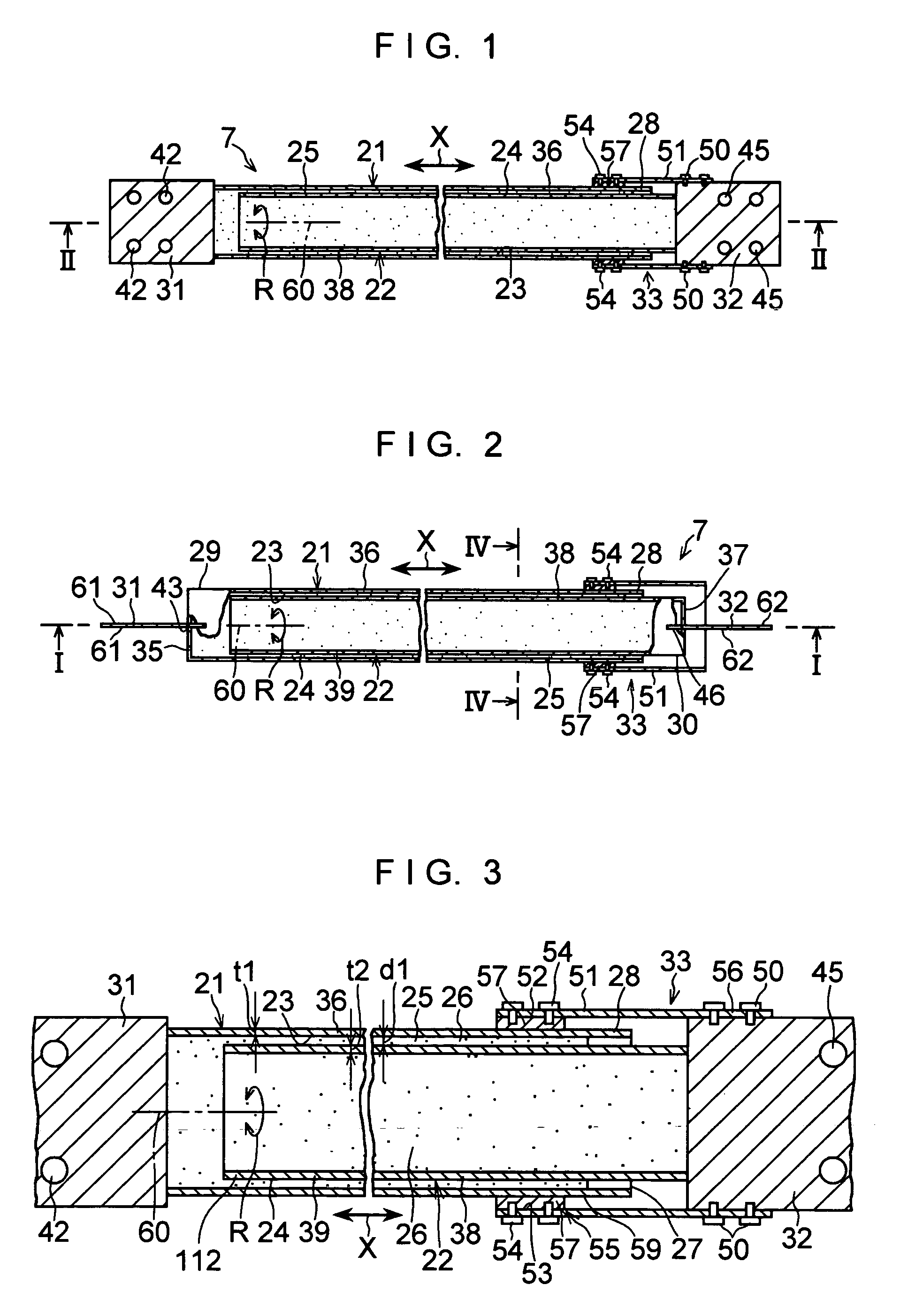
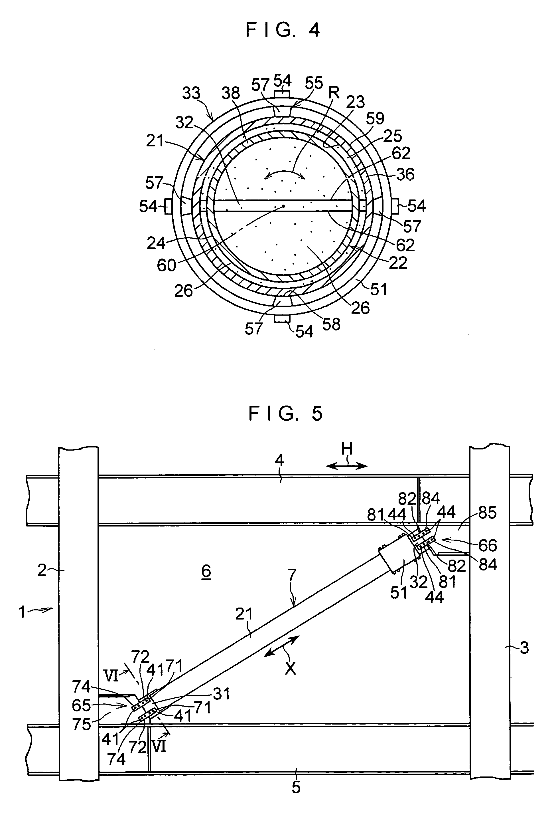
[0075]In FIGS. 1 to 6, a damping wall structure 1 as a vibration damping structure in accordance with this embodiment has a damper 7 which is capable of extending and contracting in an axial direction X and is disposed in the form of a diagonal brace in a wall space 6 defined by left and right columns 2 and 3 and upper and lower horizontal members 4 and 5 of a building.

[0076]The building in this embodiment is a high-rise building. Dampers, although not shown, are similarly disposed, as required, in the form of diagonal braces in wall spaces of the same story adjacent to the wall space 6 in this predetermined story and in wall spaces in stories higher and lower than this predetermined story, in addition to the wall space 6 in a predetermined story. In addition, although in the illustrated example, one damper 7 is disposed in the wall space 6, two or more dampers 7 may be disposed.

[0077]The damper 7 includes a hollow outer elongated body 21 formed of a cylindrical member; a hollow inn...


PUM


Abstract

A damper includes a hollow outer elongated body formed of a cylindrical member; a hollow inner elongated body similarly formed of a cylindrical member; a viscous body disposed in a cylindrical gap between an inner surface of the elongated body and an outer surface of the elongated body in such a manner as to be in contact with the inner surface and the outer surface of these elongated bodies, respectively; rectangular attaching plate members which are respectively secured to a closed-side other end portion, in an axial direction, of the elongated body having one end portion on an open end side and to a closed-side one end portion of the elongated body, respectively; and a holding structure for holding the gap between the inner surface of the elongated body at the one end portion of the elongated body and the outer surface of the elongated body.

Description

[0001]This application is the US national phase of international application PCT / JP03 / 01328 filed 7 Feb. 2003 which designated the U.S. and claims benefit of JP 2002-045367 dated 21 Feb. 2002 and JP 2002-358091 dated 10 Dec. 2002. the entire content of each of which is hereby incorporated by reference.TECHNICAL FIELD[0002]The present invention relates to a damper for damping the vibration of a building or the like caused by an earthquake by being installed in a wall of the building or the like in the form of a diagonal brace or by being installed on a column of a building or the like in a vertical direction in parallel to the column, as well as to a vibration damping structure in which this damper is interiorly fitted by being installed in a wall of a building in the form of a diagonal brace or by being installed on a column in such a manner as to extend substantially in parallel to the column in a substantially vertical direction.BACKGROUND ART[0003]Techniques have already been pro...

Claims


Application Information

Patent Timeline
Patent Type & Authority Patents(United States)
IPC IPC(8): F16F9/24E04H9/02F16F9/10F16F9/30F16F9/32F16F9/54F16F15/023
CPCF16F9/303F16F9/103E04H2009/026E04H9/0235
Inventor MOCHIMARU, MASAMIKAWAGUCHI, SUMIOMIYAZAKI, MITSURUSUZUKI, AKIO
Owner OILES CORP
Why Eureka
Try Eureka