Overlock sewing machine

a sewing machine and overlock technology, applied in the direction of sewing machines, sewing apparatus, sewing machine control devices, etc., can solve the problems of increasing the cost and the overall size, requiring laborious and troublesome installation and timing adjustment, and being relatively troublesome for users, so as to achieve the effect of simplifying the mechanism and facilitating external thread engagemen

Active Publication Date: 2006-08-31
BROTHER KOGYO KK
View PDF9 Cites 6 Cited by
  • Summary
  • Abstract
  • Description
  • Claims
  • Application Information

AI Technical Summary

Benefits of technology

[0018] By switching the underlooper to the threading position, the thread engagement can be easily carried out externally. At this time, the threading base, the guide rail, and the slider can be eliminated, allowing for a simplified mechanism. Moreover, since the underlooper is automatically returned from the threading position to the sewing position at the time of sewing start, sewing can be started without interruption even in case the user forgets the returning operation of the underlooper to the sewing position after carrying out the thread engagement.

Problems solved by technology

Since conventional overlock sewing machines have a dedicated eccentric cam and drive shaft for the overlooper and the underlooper respectively, increased number of parts are required for the drive mechanism of the foregoing, thereby increasing the cost and the overall size.
Furthermore, such construction requires laborious and troublesome installation and timing adjustment.
In such type of overlock sewing machines, thread engagement work for setting a looper thread to the underlooper need to be performed before starting the sewing operation which is relatively troublesome for the user.
However, in such construction, the provision of the threading base for thread engagement, the guide rail, and the slider increases the number of parts as well as the cost, consuming considerable time upon installation.
Thus, thread engagement work cannot be sufficiently simplified.

Method used


Image

  • Overlock sewing machine
  • Overlock sewing machine
  • Overlock sewing machine

Examples


Embodiment Construction

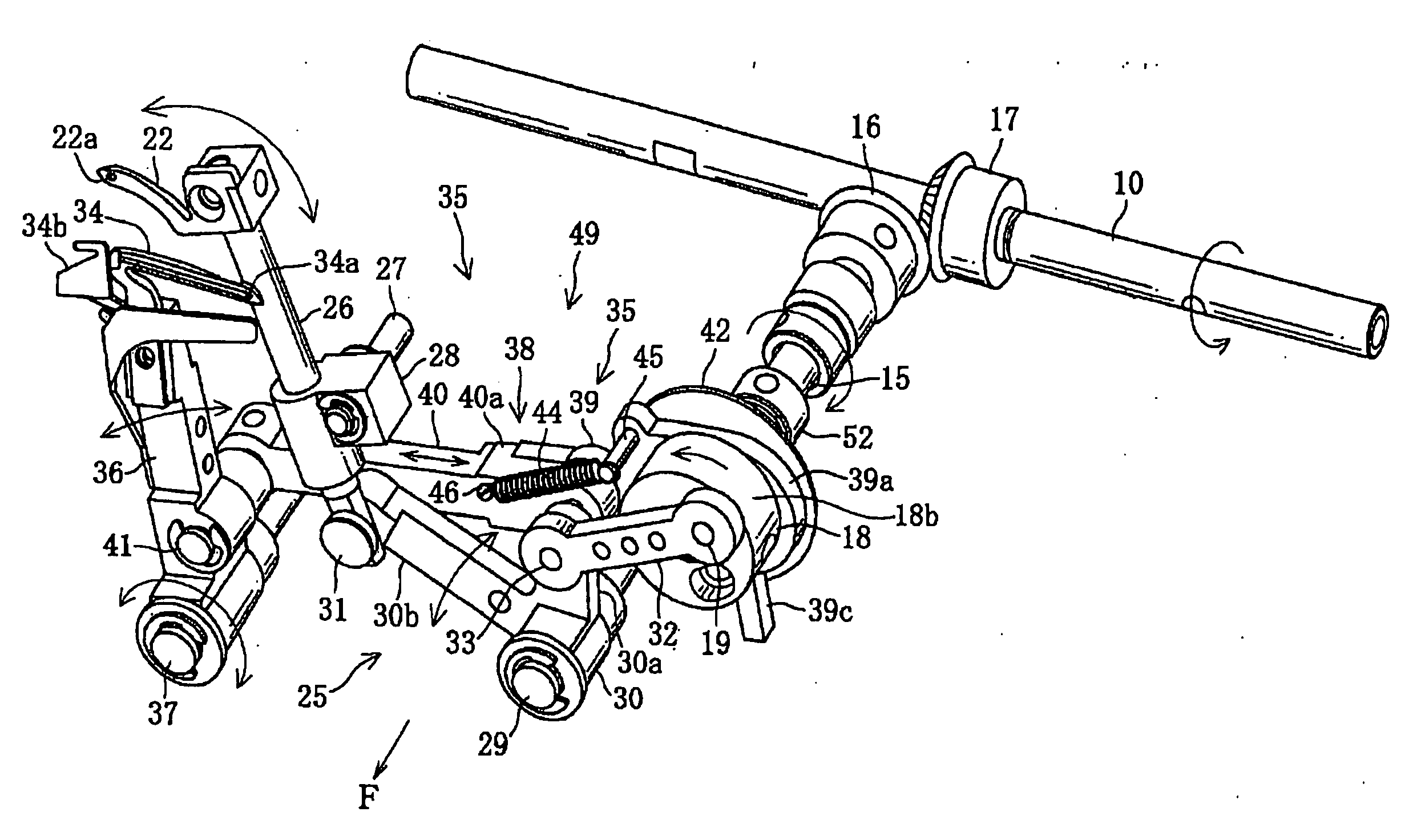
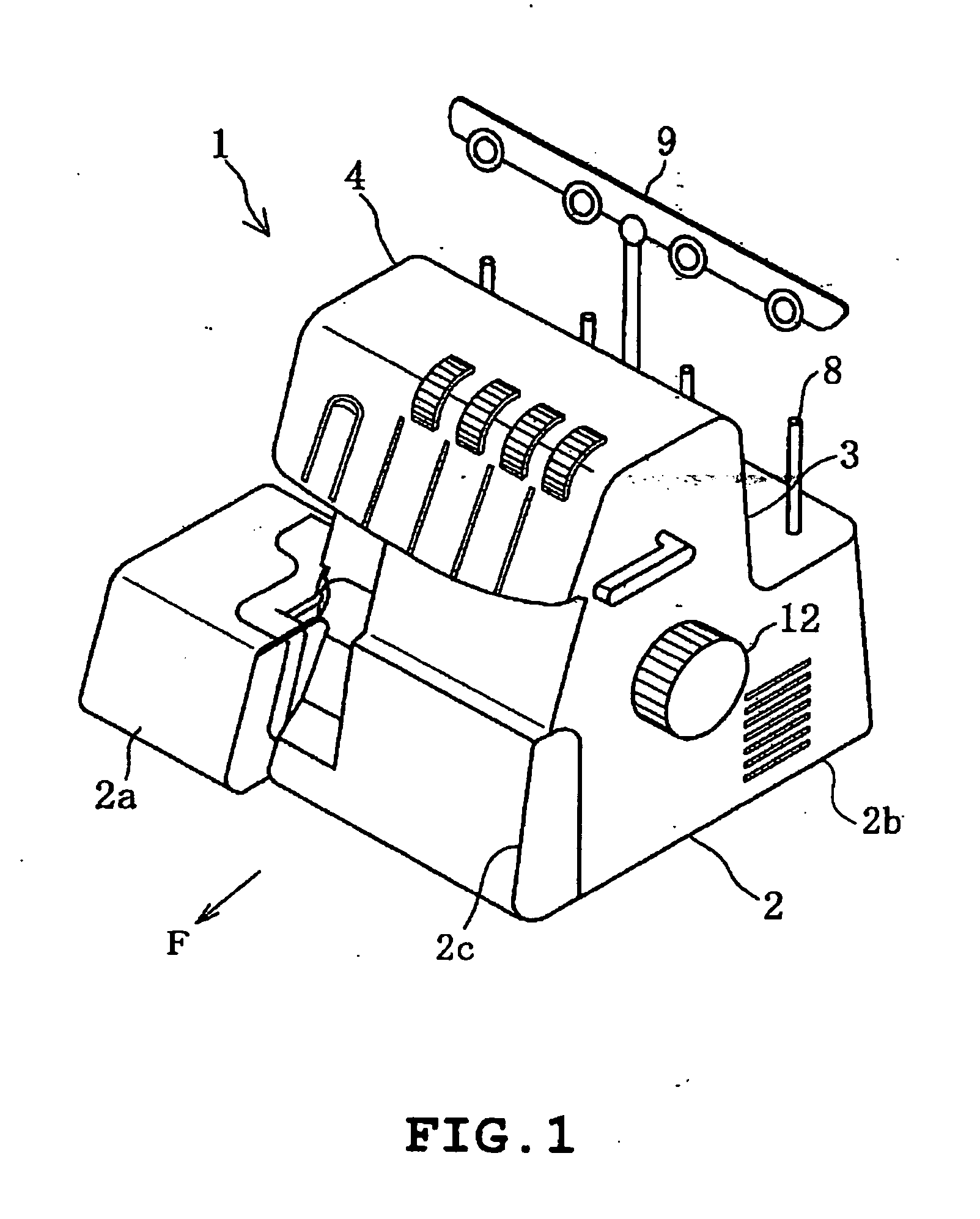
[0033] One embodiment of the present invention will be described hereinafter with reference to the drawings. Description which will be given hereinafter is to be construed with an understanding that the direction indicated by the arrow F in the drawings such as FIGS. 1 and 3 is the front side.

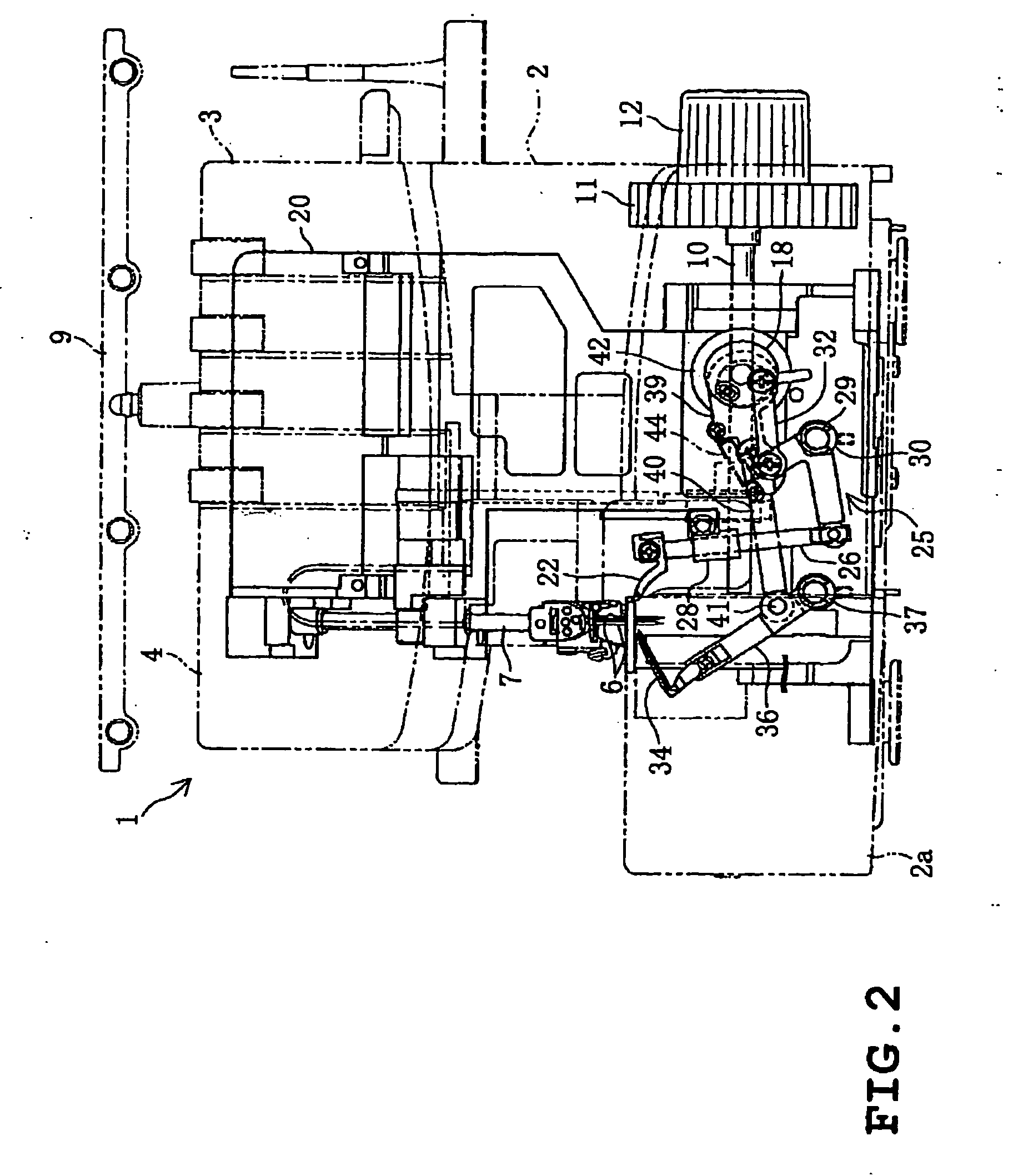
[0034] An overlock sewing machine 1, as shown in FIGS. 1 to 3 is integrally provided with a bed 2 having a free bed 2a with the left end thereof protruding in the forward direction, a pillar 3 extending upward from the bed 2, and an arm 4 extending in the horizontal direction from the upper portion of the pillar 3.

[0035] As shown in FIG. 2, the arm 4 has a needle bar 7 inclined toward the front and having, for example, two sewing needles 6 in the lower end thereof. The needle bar 7 is vertically moved by a rotation of the main shaft 10 via a drive mechanism not shown. Also, though neither of which are shown, the arm 4 has a presser foot and a vertical drive mechanism therefor, a thread take-u...


PUM


Abstract

An overlock sewing machine including a main shaft rotated by a sewing machine motor; a vertically moving sewing needle and an overlooper and an underlooper respectively driven by the rotation of the main shaft; a single looper drive shaft forming overlock stitches in cooperation with the overlooper, the underlooper and the sewing needle and rotated by the rotation of the main shaft, shaft line thereof being arranged perpendicularly to the main shaft; and a swing generating member having first and second swing generating portions fixed to the looper drive shaft for swinging the overlooper and the underlooper respectively; a first and second swing link mechanisms, both of which extend perpendicularly to the looper drive shaft, swinging the overlooper and the underlooper by conveying the drive force generated by the first and second sewing generating portions.

Description

CROSS-REFERENCE TO RELATED APPLICATIONS [0001] This application is based upon and claims the benefit of priority from the prior Japanese Patent Application No. 2005-050209, filed on, Feb. 25, 2005 the entire contents of which are incorporated herein by reference. TECHNICAL FIELD [0002] The disclosure relates to an overlock sewing machine that forms an overlock stitch by cooperation of a sewing needle, an overlooper and an underlooper. BACKGROUND [0003] A conventional overlock sewing machine, or the so called lock sewing machine, is provided with a main shaft rotated by a sewing machine motor, a sewing needle vertically moved by the rotation of the main shaft, and an overlooper and an underlooper swung by the rotation of the main shaft. Overlock stitches are formed on a cloth by swinging the overlooper and the underlooper in synchronization with the vertical movement of the sewing needle. [0004] Aforementioned types of sewing machines are disclosed for example in JP-B-S58-19317 and J...

Claims


Application Information

Patent Timeline
Patent Type & Authority Applications(United States)
IPC IPC(8): D05B57/00
CPCD05B57/34
Inventor YAMAGUCHI, MATSUOHAYASHI, HIROKI
Owner BROTHER KOGYO KK
Why Eureka
Try Eureka