Methods and Apparatus for Distance Determination for Radiofrequency Identification Devices

a radiofrequency identification and distance determination technology, applied in diversity/multi-antenna systems, polarisation/directional diversity, wireless communication, etc., can solve problems such as reducing range accuracy, rendering difficult or in some cases impossible the use of phase information to accurately compute distance, and making such avoidance more difficul

Active Publication Date: 2010-03-04
NCR CORP
View PDF16 Cites 18 Cited by
  • Summary
  • Abstract
  • Description
  • Claims
  • Application Information

AI Technical Summary

Problems solved by technology

However, the prevalence of reflected signals in the environment of the reader, conveniently referred to as static proximity reflected signals, tends to degrade ranging accuracy.
The signals will therefore include mixed phase information, rendering difficult or in some cases impossible the use of phase information to accurately compute distance.
Such a configuration is particularly useful for readers that are installed at security checkpoints, because a thief trying to steal an object with an RFID tag attached is likely to attempt to avoid the signals emitted by a reader, and a broad focus for the signals makes such avoidance more difficult.

Method used


Image

  • Methods and Apparatus for Distance Determination for Radiofrequency Identification Devices
  • Methods and Apparatus for Distance Determination for Radiofrequency Identification Devices
  • Methods and Apparatus for Distance Determination for Radiofrequency Identification Devices

Examples


Embodiment Construction

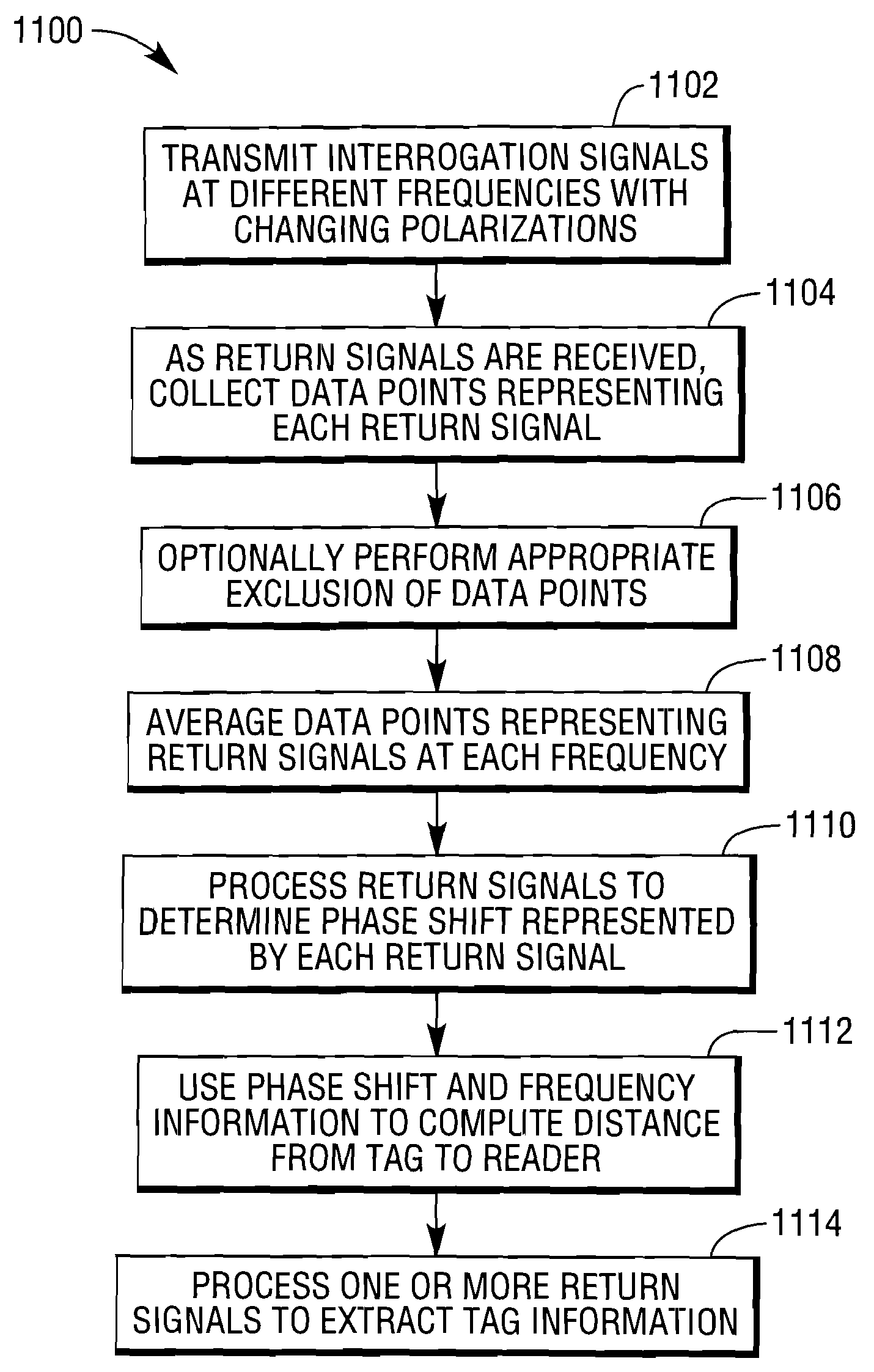
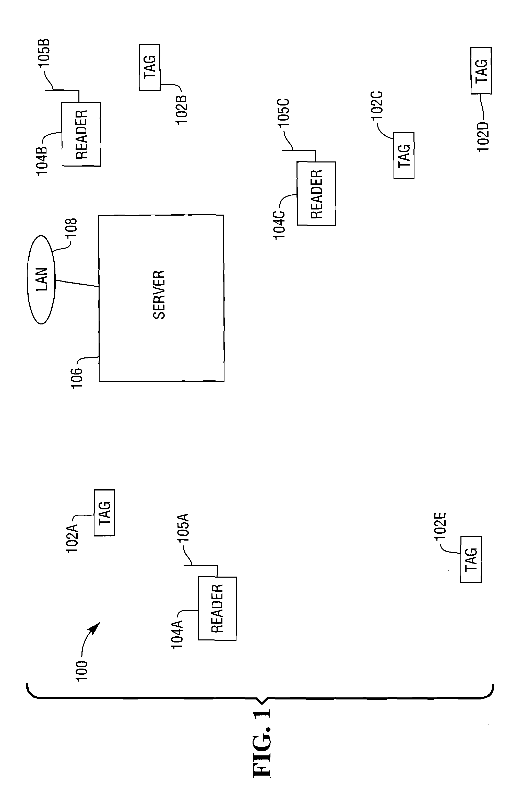
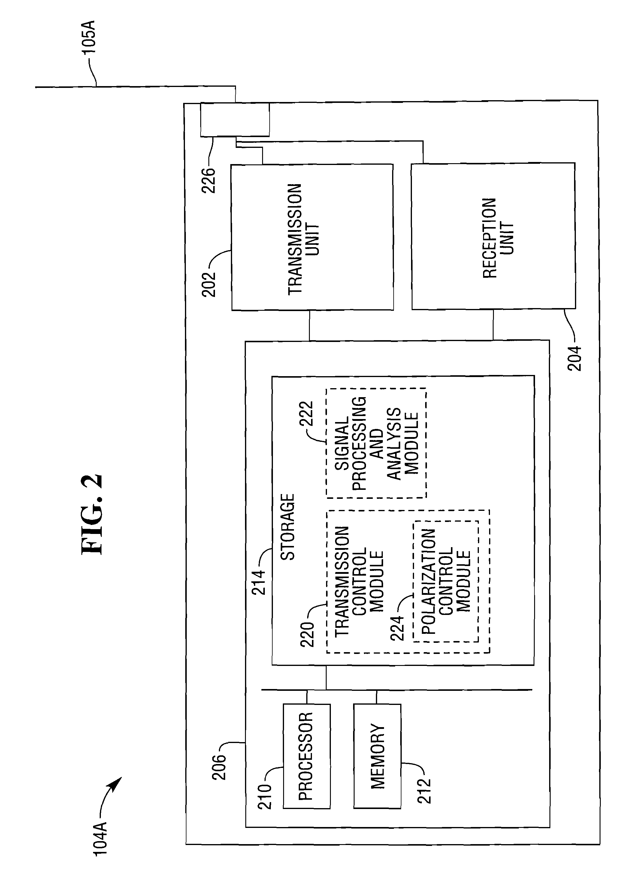
[0016]FIG. 1 illustrates an RFID system 100 according to an aspect of the present invention. The system 100 includes a plurality of RFID tags 102A-102E, and a plurality of RFID readers 104A, 104B, and 104C, including antennas 105A, 105B, and 105C, respectively. The readers 104A-104C may suitably communicate with a server 106 over a local area network (LAN) 108, which may be a wired or wireless network, or may provide both wired and wireless access. When one of the readers is used to interrogate for the presence of an RFID tag, the reader emits interrogation signals at differing frequencies. The differing frequencies will produce differing phases, and the differing frequencies and phases of the signals returned to the reader can be used to compute the distance between the reader and a tag responding to the reader. The distance between the reader and the tag is given by the following computation:

d=(12)(cf1-f2)(θ1-θ22π),

where c is the velocity of light.

[0017]If the signal returned to a...


PUM


Abstract

Systems and techniques for reading radio frequency identification (RFID) tags and determining the distance between a reader and a tag being read. A plurality of interrogation signals are transmitted to an RFID tag, with signals at a first frequency being transmitted at a plurality of antenna polarizations and signals at a second frequency being transmitted at a plurality of antenna polarizations. The antenna polarizations are chosen such that return signals resulting from the signals and traveling along reflective paths will sum to zero. Return signals received from the tag are averaged, and phase shift information exhibited by the return signals is determined. The phase shift information for the return signals and frequency information for the interrogation signals is used to compute the distance between the reader and the tag.

Description

FIELD OF THE INVENTION[0001]The present invention relates generally to improved reading of radio frequency identification (RFID) devices. More particularly, the invention relates to improved systems and techniques for determination of the distance between an RFID device and a reader.BACKGROUND OF THE INVENTION[0002]Radio frequency identification (RFID) systems are widely used for the identification and tracking of articles. An RFID tag may be affixed to an article for which tracking is desired. Examples of articles that may be tracked include an inventory item or a pallet on which inventory items are placed for storage or transport. The RFID tag may suitably include identification information, such an identification code that can be used to retrieve stored information. Alternatively, or in addition, the identification information may include actual descriptive information relating to the article. The tags are read with RFID readers, and noting the time of reading and location of the...

Claims


Application Information

Patent Timeline
Patent Type & Authority Applications(United States)
IPC IPC(8): H04B7/00
CPCH04W64/00H04B7/10
Inventor OZEKI, TAKEOUTSUMI, YOSHITAKI
Owner NCR CORP
Why Eureka
Try Eureka