
Liquid crystal display

a liquid crystal display and display area technology, applied in non-linear optics, instruments, optics, etc., can solve the problems of low optical transmissivity in the bright display area, inability to visually recognize the display image in some cases, and inability to achieve proper tendency, etc., to achieve good image display

Inactive Publication Date: 2010-03-04
STANLEY ELECTRIC CO LTD
View PDF5 Cites 7 Cited by
  • Summary
  • Abstract
  • Description
  • Claims
  • Application Information

AI Technical Summary

Benefits of technology

[0035]An object of the present invention is to provide a liquid crystal display capable of realizing good image display.
[0038]According to the present invention, it is possible to provide a liquid crystal display capable of realizing good image display.

Problems solved by technology

However, as the liquid crystal display is observed at a large polar angle along the normal direction of the right / left direction (180°-0° direction) set along 45° direction relative to the absorption axes Fab and Rab of the upper and lower polarizers 10 and 20, an optical transmissivity in the bright display area becomes extremely low, and display image cannot be visually recognized at all in some cases.
It has been found that the second conventional example has the tendency that color shift is observed remarkably at a large angle, and this tendency is not proper from the viewpoint of outer appearance of the display.
It is considered that even if the liquid crystal displays of the first and second conventional examples are manufactured by using commercially available optical films, it is difficult to obtain good image display performance.

Method used


Image

  • Liquid crystal display
  • Liquid crystal display
  • Liquid crystal display

Examples


Embodiment Construction

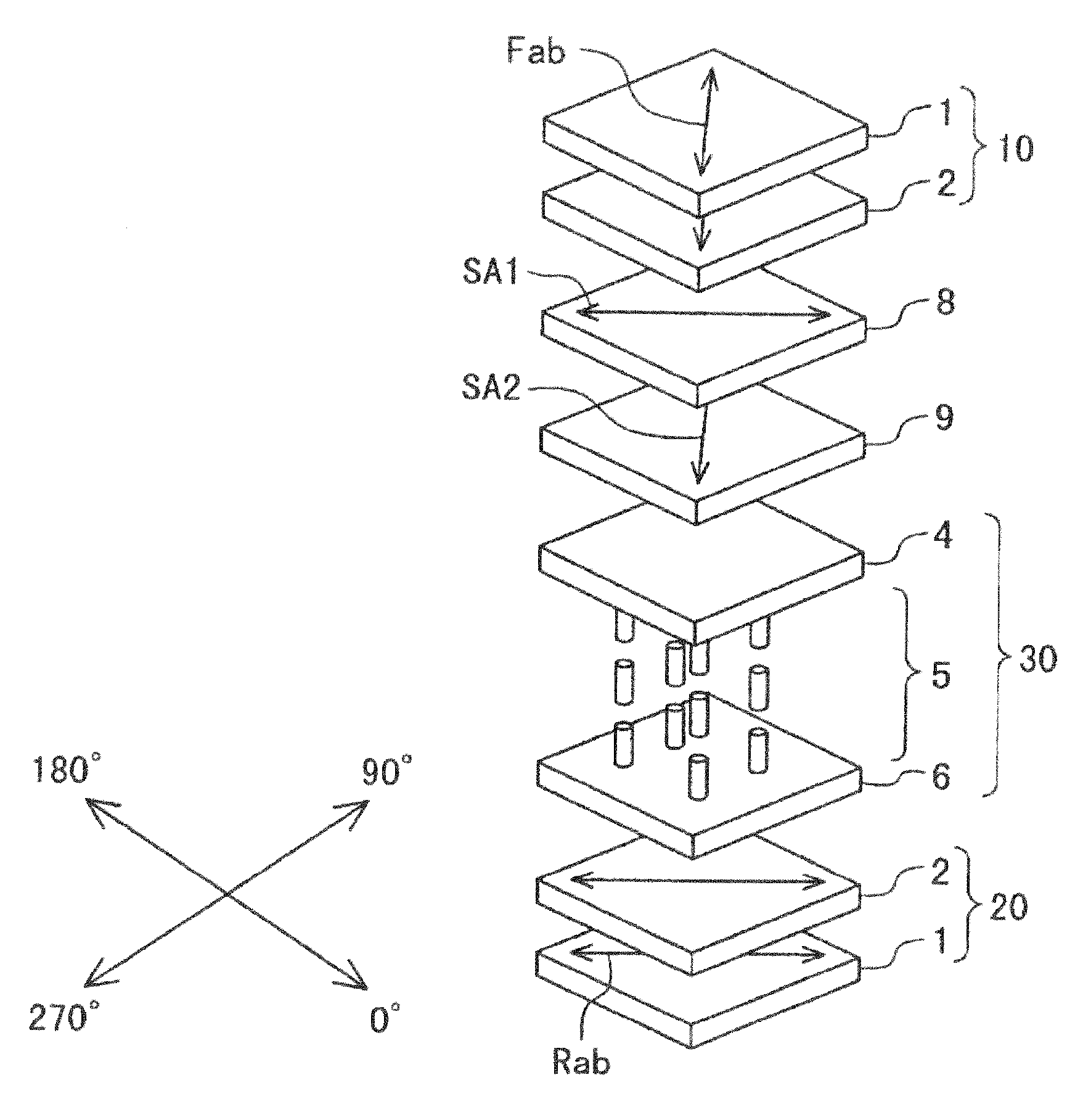
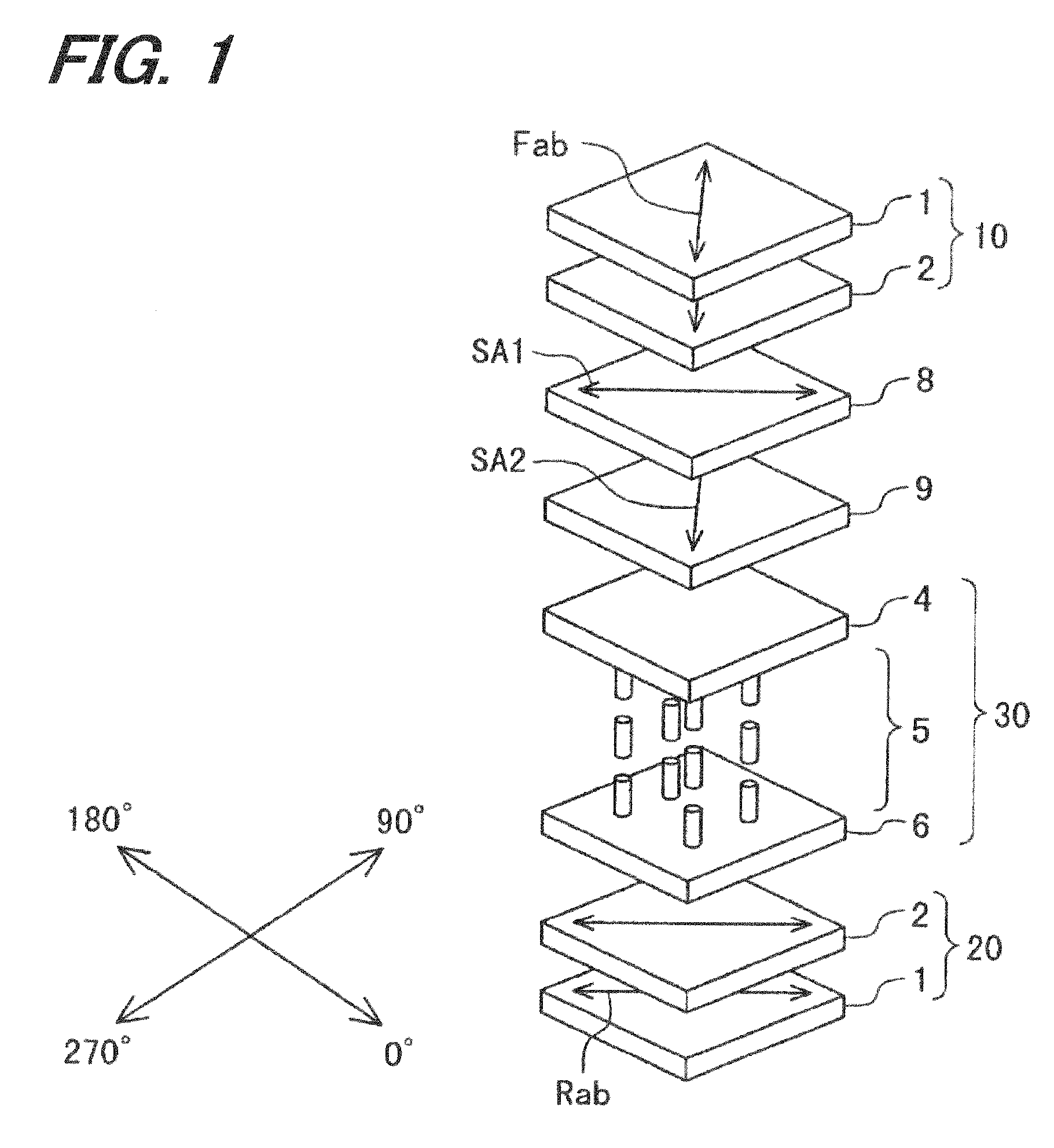
[0050]FIG. 1 is a schematic diagram illustrating a liquid crystal display according to an embodiment.

[0051]Between an upper polarizer 10 and a lower polarizer 20 generally crossed-Nichol disposed, a liquid crystal layer, e.g., a mono domain vertical alignment liquid crystal cell 30, is disposed having a vertical alignment liquid crystal layer subjected to a vertical or generally vertical alignment process. The mono domain vertical alignment liquid crystal cell 30 is constituted of an upper glass substrate (transparent substrate) 4, a lower glass substrate (transparent substrate) 6 and a mono domain vertical alignment liquid crystal layer 5 squeezed between both substrates 4 and 6. Between the upper glass substrate 4 of the vertical alignment liquid crystal cell 30 and the upper polarizer 10, a first optical film 8 and a second optical film 9 are disposed sequentially in this order from the upper polarizer 10 side. Both the optical films 8 and 9 may use, e.g., norbornene COP stretche...


PUM

PropertyMeasurementUnit
thicknessaaaaaaaaaa
thicknessaaaaaaaaaa
thicknessaaaaaaaaaa

Abstract

A liquid crystal display includes: a liquid crystal layer squeezed between first and second substrates and vertically aligned at a retardation of 300-1000 nm; first and second compensators disposed on the first substrate and having negative biaxial optical anisotropy; a first polarizer disposed on the first and second compensators; and a second polarizer on the second substrate disposed crossed-Nichol with said first polarizer, wherein: the second compensator is disposed between the first substrate and first compensator; an in-plane slow axis of the first compensator is disposed perpendicular to an absorption axis of the first polarizer; the in-plane slow axis of the first compensator is disposed perpendicular to an in-plane slow axis of the second compensator; and a retardation in an in-plane direction of the first compensator is larger than that of the second compensator.

Description

CROSS REFERENCE TO RELATED APPLICATION[0001]This application is based on and claims priority of Japanese Patent Application JP2008-223324 filed on Sep. 1, 2008, the entire contents of which are incorporated herein by reference.BACKGROUND OF THE INVENTION[0002]A) Field of the Invention[0003]The present invention relates to a liquid crystal display (LCD)[0004]B) Description of the Related Art[0005]Many of liquid crystal display apparatus capable of segment display or both segment display and dot-matrix display under multiplex driving now mount a normally black type liquid crystal display having a very low display luminance in a background display area and dark display areas Most of them are monochromatic displays using a single color LED as a backlight, and adopt a twist nematic (TN) type as a liquid crystal display structure.[0006]A vertically aligned liquid crystal display is known which disposes a liquid crystal cell of a vertical alignment mode in which liquid crystal molecules in...

Claims


Application Information

Patent Timeline
Patent Type & Authority Applications(United States)
IPC IPC(8): G02F1/1335
CPCG02F1/1393G02F1/133634
Inventor IWAMOTO, YOSHIHISA
Owner STANLEY ELECTRIC CO LTD
Learn More