
L2 Tunneling-based Low Latency Single Radio Handoffs

a low latency, single radio technology, applied in the direction of electrical equipment, wireless communication services, wireless communication, etc., can solve the problems of not always being possible, extremely high handoff delay,

Active Publication Date: 2010-03-04
TAHOE RES LTD
View PDF5 Cites 117 Cited by
  • Summary
  • Abstract
  • Description
  • Claims
  • Application Information

AI Technical Summary

Problems solved by technology

Although, these technologies support an inter-access mobility solution, the handoff delay could be extremely high.
However, this may not always be possible, because due to interference, platform noise and / or co-existence issues, it might only be possible to have a single radio operating at any point in time.

Method used


Image

  • L2 Tunneling-based Low Latency Single Radio Handoffs
  • L2 Tunneling-based Low Latency Single Radio Handoffs
  • L2 Tunneling-based Low Latency Single Radio Handoffs

Examples


Embodiment Construction

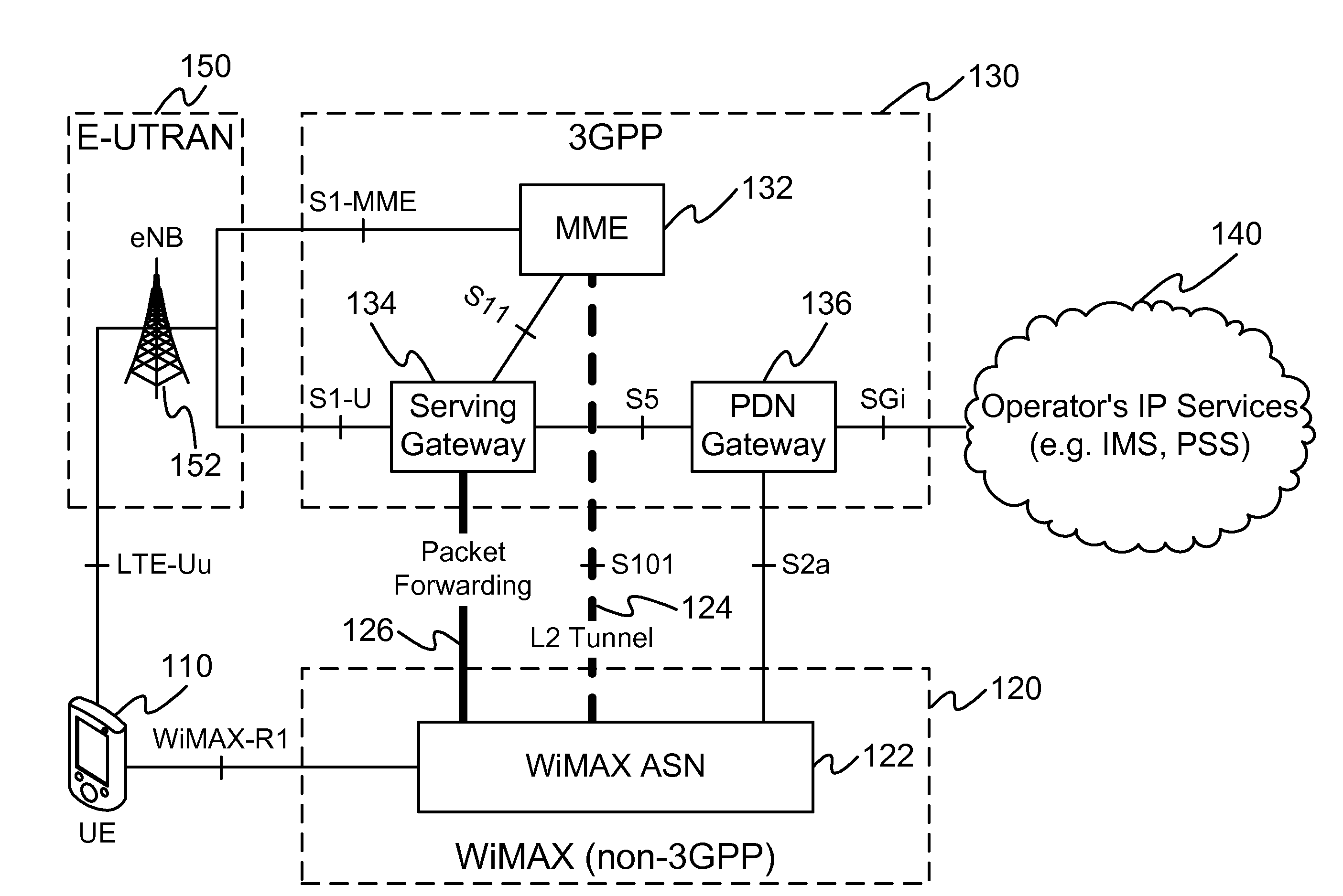
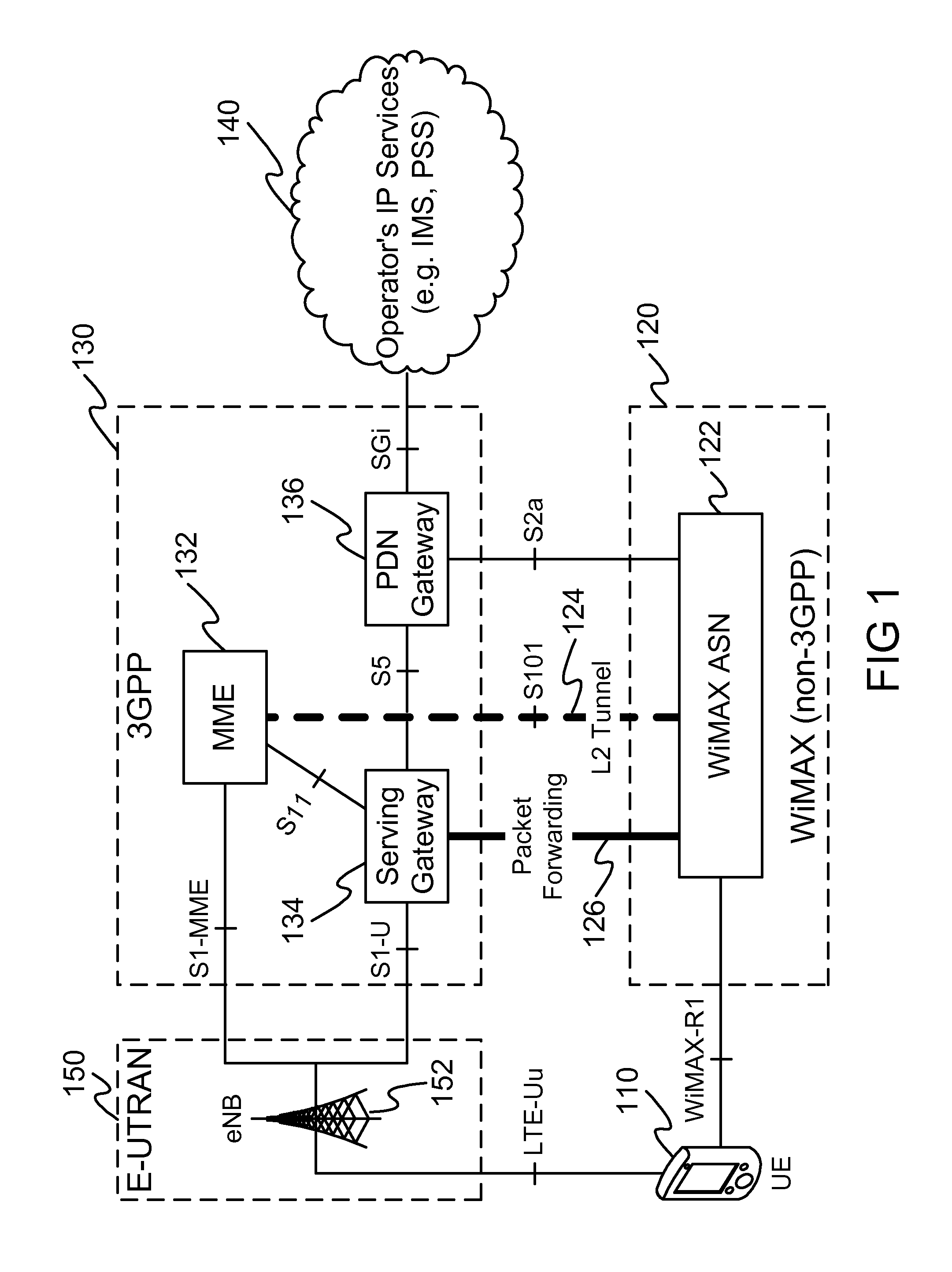
[0009]An embodiment of this invention uses an alternative architecture to for single radio handover between two wireless networks such as WiMAX and 2G / 3G / 4G. This embodiment uses a Data Link Layer (L2) tunneling between the source / target and core (e.g., evolved packet core) networks to achieve a tighter handover control and synchronization, support for network initiated handoffs based on operator policy and Radio resource management (RRM), and overall lower latency of handovers and packet loss. In one embodiment, the actual path between the two entities is still IP based, but the tunnel carries L2 messages, as opposed to L3 messages.

[0010]In an embodiment of this invention, (referring to FIG. 1), a user equipment (UE) (110), which is connected to a source wireless network such as an E-UTRAN (evolved-universal mobile telecommunication system (UMTS) terrestrial radio access network) (150) via an evolved-node B (eNB) (152), is handed over to a target wireless network, such as WiMAX (12...


PUM


Abstract

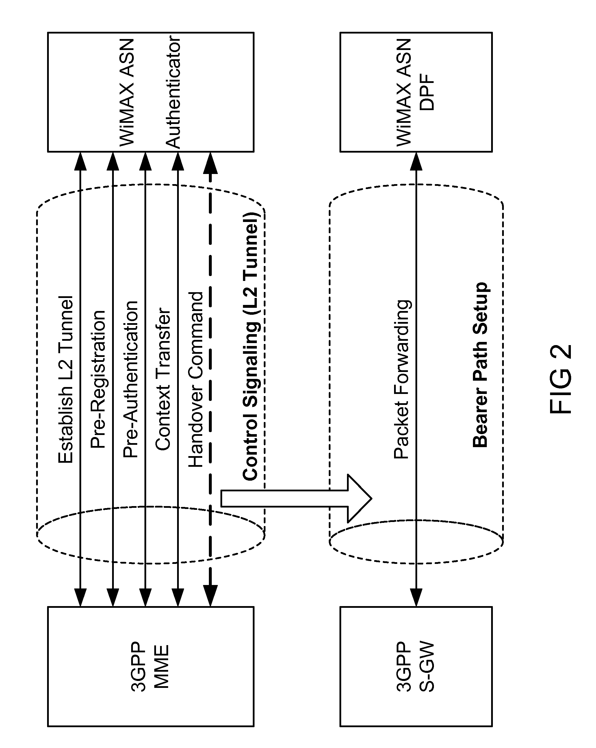
An example of this invention provides low latency handovers between Mobile WiMAX and 2G / 3G / LTE networks with only a single radio transmitting at any given point in time, by establishing L2 tunnel between 3GPP MME and WiMAX ASN for control plane signaling to perform pre-registration, pre-authentication and context transfer to the target network, while UE maintains its connection to the source network, and by setting up bearer path for packet forwarding between Servicing Gateway and WiMAX ASN. An example of this invention uses a virtual eNB to facilitate low latency L2 handoffs to legacy 2G / 3G networks with minimum impact to SGSN and MME.

Description

BACKGROUND OF THE INVENTION[0001]Mobile service providers already possess and operate several heterogeneous access technologies and networks. The mixed network environments are expected to become more prevalent as different radio technologies best serve different deployment types and environments. For example, Wi-Fi™ has shown to be a great technology for indoor operation, whereas cellular technologies such as 2G / 3G (2nd Generation / 3rd Generation) and WiMAX (Worldwide Interoperability for Microwave Access) operate best in licensed spectrum covering large outdoor environments. It is also expected that multi-mode wireless devices shall become widespread. Hence, it is of great interest to the mobile operators, technology users, and vendors to provide seamless mobility between these heterogeneous access technologies with uninterrupted service continuity.[0002]The current technologies have focused on pure layer 3 (L3) mobility solutions such as Mobile IP (Internet Protocol). Although, th...

Claims


Application Information

Patent Timeline
Patent Type & Authority Applications(United States)
IPC IPC(8): H04W36/00
CPCH04W36/14H04W36/0011H04W36/144H04W36/0019
Inventor GUPTA, VIVEKTAAGHOL, POUYA
Owner TAHOE RES LTD
Learn More