Low latency pyramid processor for image processing systems

a pyramid processor and image processing technology, applied in image enhancement, image analysis, instruments, etc., can solve problems such as sub-frame delay

Inactive Publication Date: 2005-12-01
SARNOFF CORP
View PDF11 Cites 148 Cited by
  • Summary
  • Abstract
  • Description
  • Claims
  • Application Information

AI Technical Summary

Benefits of technology

[0010] One specific application of the invention is a Vision Aided Navigation (VAN) system that combines vision information with more traditional position location systems (e.g., initertial navigation, satellite

Problems solved by technology

Such sub-frame processing results in a sub-frame delay between the

Method used


Image

  • Low latency pyramid processor for image processing systems
  • Low latency pyramid processor for image processing systems
  • Low latency pyramid processor for image processing systems

Examples


Embodiment Construction

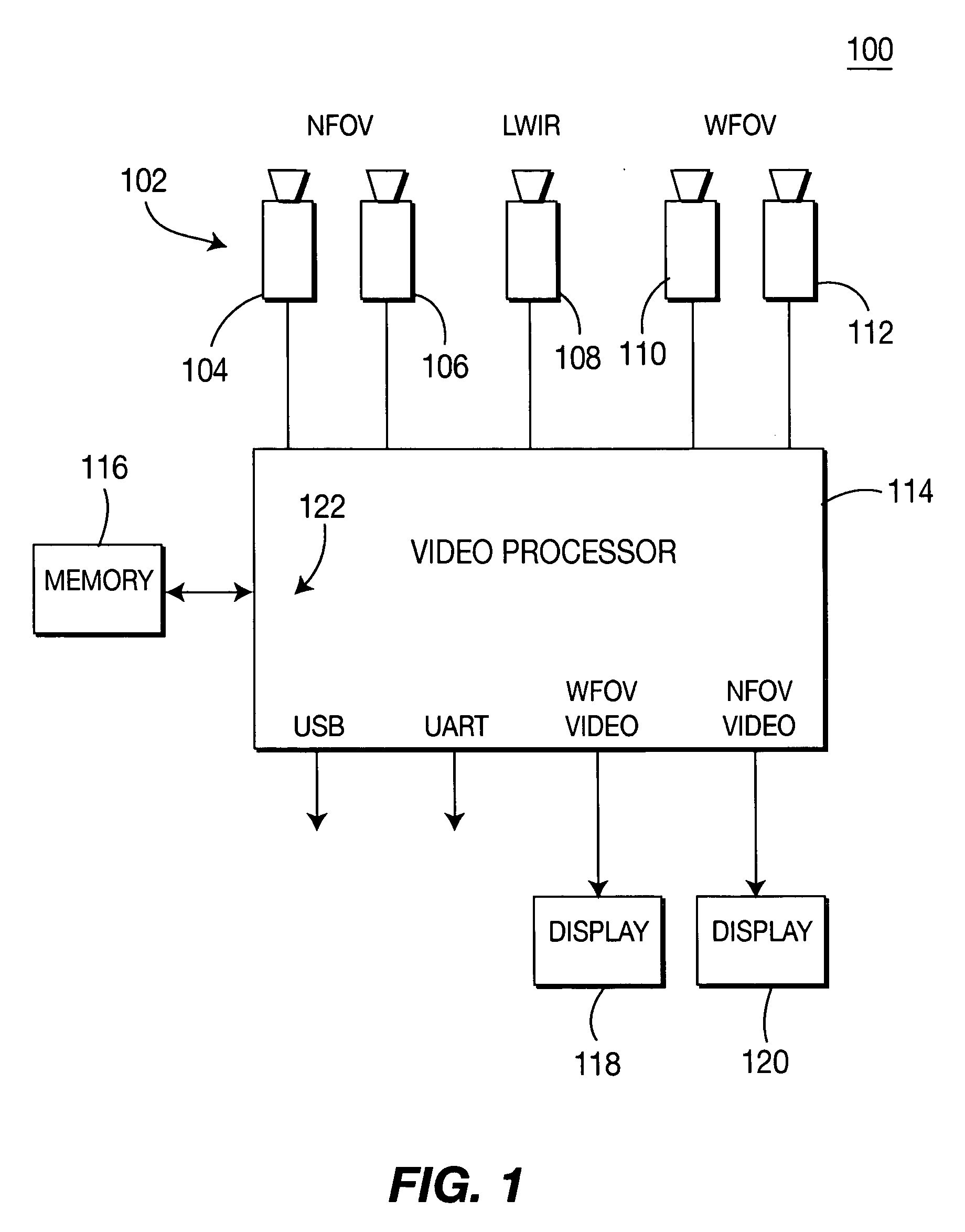
[0018]FIG. 1 depicts a high-level block diagram of a video processing system 100 comprising a plurality of sensors 104, 106, 108, 110,and 112 (collectively sensors 102), a video processor 114, memory 116, and one or more displays 118, 120. The video processor 114 is generally, but not necessarily a single integrated circuit. As such, the system 100 can be assembled into a relatively compact space, e.g., on a hand-held platform, helmet platform, platform integrating a sensor and the video processor (system on a chip platform) and the like.

[0019] Specifically, multiple sensor imagery from sensors 102 is combined and fused into one or more display images. In an exemplary embodiment shown in FIG. 1, the video processor 114 forms a stereo image, i.e., a right and left image for display on a heads-up display in front of each eye of a user. Although any form of sensor can be used in the system 100, in an exemplary embodiment, the video sensors 102 include a pair of narrow field of view (N...


PUM


Abstract

A video processor that uses a low latency pyramid processing technique for fusing images from multiple sensors. The imagery from multiple sensors is enhanced, warped into alignment, and then fused with one another in a manner that provides the fusing to occur within a single frame of video, i.e., sub-frame processing. Such sub-frame processing results in a sub-frame delay between a moment of capturing the images to the display of the fused imagery.

Description

CROSS-REFERENCE TO RELATED APPLICATIONS [0001] This application claims benefit of U.S. provisional patent application Ser. No. 60 / 574,175, filed May 25, 2004, which is herein incorporated by reference.GOVERNMENT RIGHTS IN THIS INVENTION [0002] This invention was made with U.S. government support under contract number NBCH030074, Department of the Interior. The U.S. government has certain rights in this invention.BACKGROUND OF THE INVENTION [0003] 1 . Field of the Invention [0004] Embodiments of the present invention generally relate to an improved method for performing video processing and, more particularly, the invention relates to a low latency pyramid processor in an image processing system. [0005] 2 . Description of the Related Art [0006] Pyramid processing of images generally relies upon a deconstruction process that repeatedly Laplacian filters an image frame of a video sequence. Such filtering produces, for each video frame, a sequence of sub-images representing “Laplacian l...

Claims


Application Information

Patent Timeline
IPC IPC(8): G06K9/32G06K9/36G06K9/40G06K9/46G06T5/00G06T5/50
CPCG06T2207/20016G06T2207/20221G06T5/50
Inventor PIACENTINO, MICHAEL RAYMONDVAN DER WAL, GOOITZEN SIEMENBURT, PETER JEFFREYBERGEN, JAMES RUSSELL
Owner SARNOFF CORP
Why Eureka
Try Eureka