
Analyzing partial face regions for red-eye detection in acquired digital images

a technology of digital image and partial face, applied in the field of digital image processing, can solve the problems of deteriorating the overall detection of red eye defects and objectionable phenomena

Active Publication Date: 2010-03-04
FOTONATION LTD
View PDF38 Cites 88 Cited by
  • Summary
  • Abstract
  • Description
  • Claims
  • Application Information

AI Technical Summary

Benefits of technology

"The present invention relates to a method and apparatus for detecting and reducing red-eye defects in digital images. The technical effect of this patent is to improve the success rate of algorithms for detecting and reducing red-eye phenomenon, by improving the quality of the detection and correction process. The invention addresses the issue of false detection and provides various modes of operation to improve the accuracy of red-eye detection in limited computational devices such as digital cameras. The invention also includes a red-eye filter chain and a face tracking system for further improving the detection and reduction of red-eye defects in digital images."

Problems solved by technology

This objectionable phenomenon is well understood to be caused in part by a small angle between the flash of the camera and the lens of the camera.
For example an image with suboptimal exposure may deteriorate the overall detection of red-eye defects.

Method used


Image

  • Analyzing partial face regions for red-eye detection in acquired digital images
  • Analyzing partial face regions for red-eye detection in acquired digital images
  • Analyzing partial face regions for red-eye detection in acquired digital images

Examples


example process

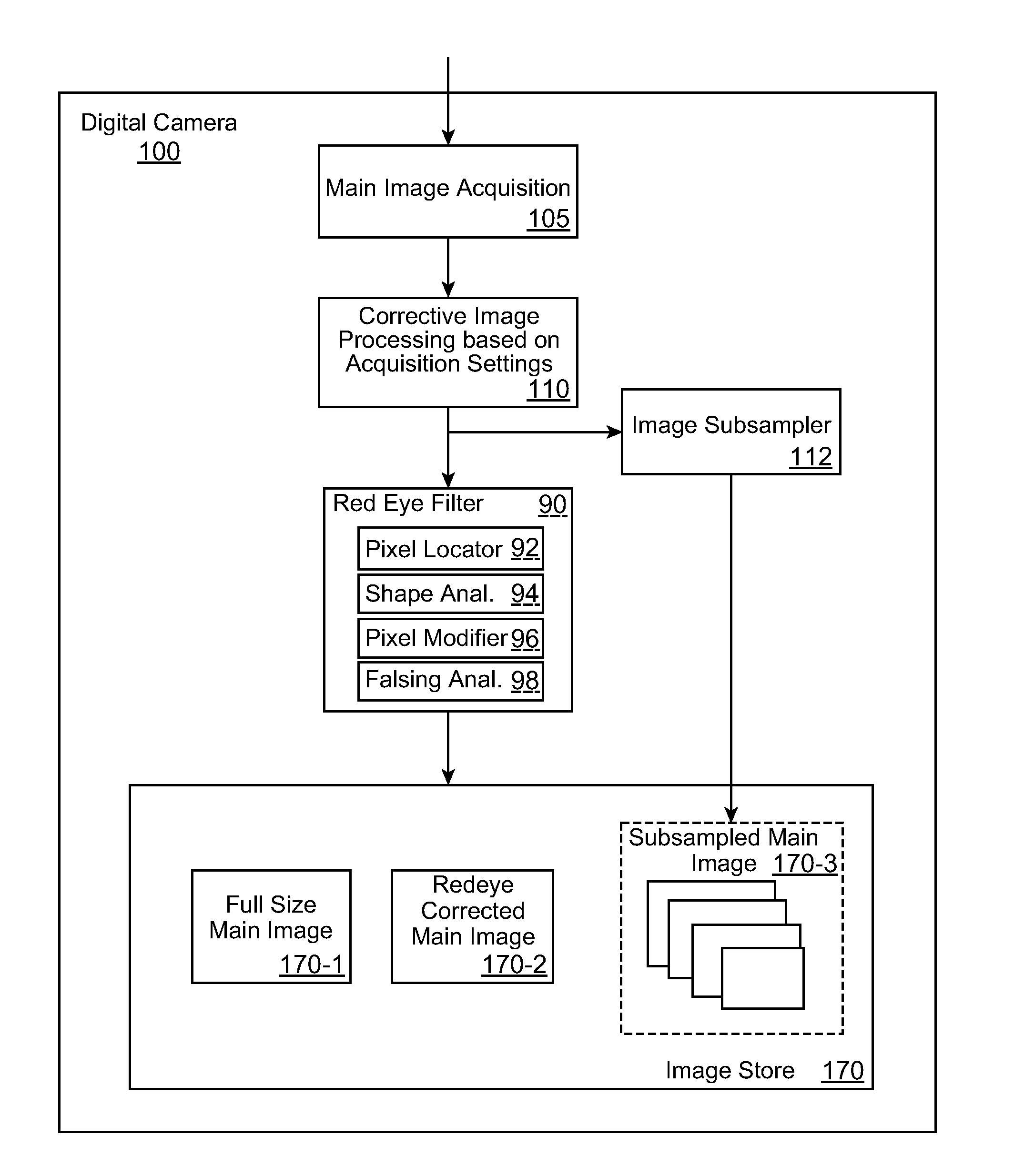
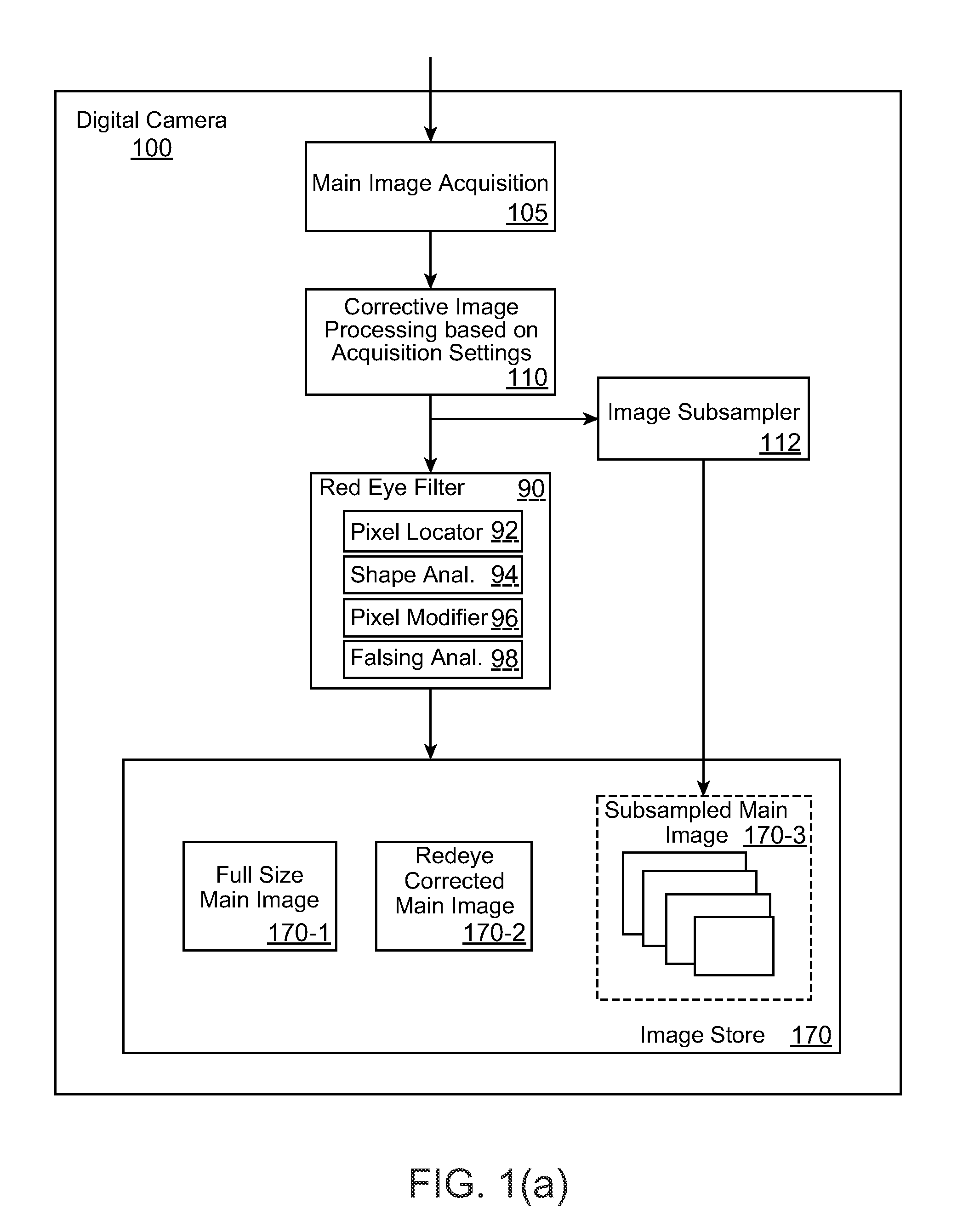
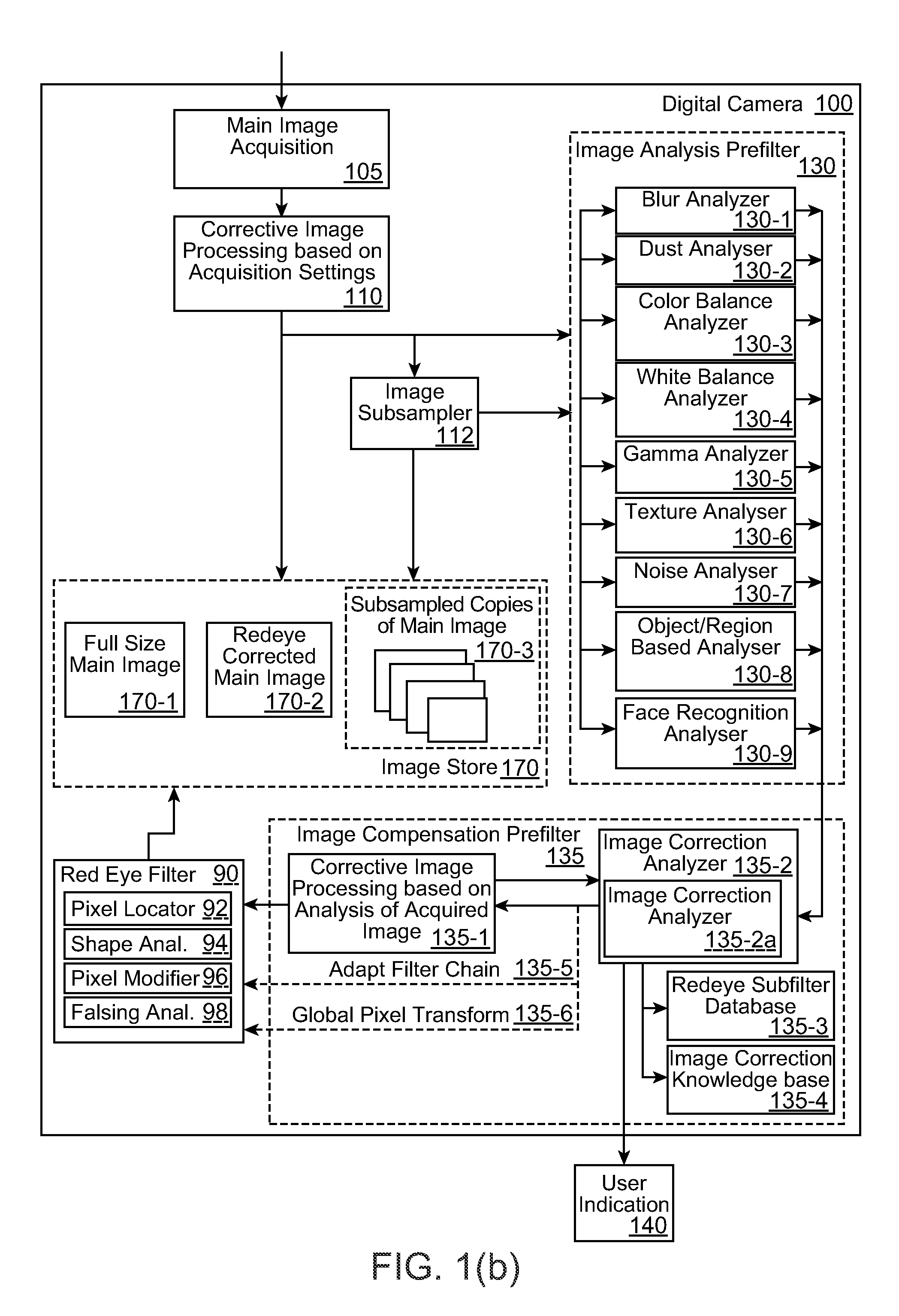
[0176]In an exemplary process, a redeye detection algorithm may be applied on an entire image, which may be a low resolution image such as a preview or postview image. A red eye list may be obtained of regions suspected as candidate red eye regions. An extended eye detector may be applied to the image from which an extended eyes list is generated. Using one or more geometric operations, such as applying rectangles or other polygons or elliptical shapes to the image, a list is generated from the extended eyes list.

[0177]Redeye detection accuracy improvement is achieved when the red eye candidate region list is combined with the extended eyes list or the list discussed above as being generated therefrom by applying one or more geometric operations. Each eye- or eye pair-rectangle may be verified by intersecting the redeye candidate list. If not, a new refined red eye detection may be applied inside the eye- or eye pair-rectangle, e.g., based on the presence of the eye- or eye pair-rec...

example method

[0272]FIG. 15 is a flow chart showing a method according to certain embodiments. The segmentation filter 2090 of the image acquisition device 2020 (also referred to as a “camera” in parts of the disclosure) shown in FIG. 14 can use the foreground / background segmentation information 2099 of a stored image I(x,y) to produce a binary map with foreground (FG) pixels and background (BG) pixels (Block 2210). The binary map might, for example, assign a first value to background pixels and a second value to foreground pixels such that an image corresponding to the binary map shows the foreground image in black and the background in white. U.S. Patent Publication No. 2006 / 0039690, titled “Foreground / Background Segmentation In Digital Images With Differential Exposure Calculations,” filed Aug. 30, 2005, is hereby incorporated by reference in its entirety. In one embodiment, the binary map is refined to improve the quality of the segmentation of a foreground object from the background of a dig...


PUM


Abstract

A method for red-eye detection in an acquired digital image includes acquiring a first image, and analyzing one or more partial face regions within the first image. One or more characteristics of the first image are determined. One or more corrective processes are identified including red eye correction that can be beneficially applied to the first image according to the one or more characteristics. The one or more corrective processes are applied to the first image.

Description

RELATED APPLICATIONS[0001]This application claims the benefit of priority to U.S. provisional patent applications Nos. 61 / 094,034 and 61 / 094,036, each filed Sep. 3, 2008 and 61 / 182,625, filed May 29, 2009 and 61 / 221,455, filed Jun. 29, 2009. This application is also a continuation-in-part (CIP) of U.S. patent application Ser. No. 11 / 233,513, filed Sep. 21, 2005, which is a CIP of U.S. Ser. No. 11 / 123,971, filed May 6, 2005, now U.S. Pat. No. 7,436,998, which is a CIP of U.S. Ser. No. 10 / 976,336, filed Oct. 28, 2004, now U.S. Pat. No. 7,536,036. This application is also related to U.S. patent application Ser. Nos. 11 / 123,971, 11 / 233,513, 10 / 976,336, as well as 10 / 635,862, 10 / 635,918, 10 / 170,511, 11 / 690,834, 10 / 635,862, 12 / 035,416, 11 / 769,206, 10 / 772,767, 12 / 119,614, 10 / 919,226, 11 / 379,346, 61 / 221,455 and 61 / 182,065, and U.S. Pat. Nos. 6,407,777, 7,352,394, 7,042,505 and 7,474,341, and a contemporaneously filed application entitled Optimized Performance and Performance for Red-Eye Fil...

Claims


Application Information

Patent Timeline
Patent Type & Authority Applications(United States)
IPC IPC(8): G06K9/00H04N23/40
CPCG06T5/008G06T7/0081G06T7/408G06T2207/10024H04N1/624G06T2207/30216H04N5/2256H04N5/23219G06T5/005G06T2207/20148G06T7/11G06T7/90G06T7/136H04N23/56H04N23/611G06T5/94G06T5/77
Inventor NANU, FLORINPETRESCU, STEFANGANGEA, MIHNEACAPATA, ADRIANCIUC, MIHAIZAMFIR, ADRIANSTEINBERG, ERANCORCORAN, PETERPOSOSIN, ALEXEIBIGIOI, PETRONELDRIMBAREAN, ALEXANDRU
Owner FOTONATION LTD
Learn More