Nasal Dilator

a dilator and nasal tube technology, applied in respirators, person identification, diagnostic recording/measuring, etc., can solve the problems of affecting the effectiveness of cpap therapy and patient compliance, affecting the effective pressure delivered to the patient's airway, and affecting the patient's breathing. the effect of resistance, reducing the impedance, and reducing the impedan

Inactive Publication Date: 2009-07-23
RESMED LTD
View PDF14 Cites 58 Cited by
  • Summary
  • Abstract
  • Description
  • Claims
  • Application Information

AI Technical Summary

Benefits of technology

[0014]The invention aims to ameliorate one or more of the above problems by a novel idea for a device that reduces flow impedance within a breathing patient's airway (nose). By reducing impedance, breathing resistance is therefore reduced and breathing comfort and patient compliance improves.

Problems solved by technology

Nasal resistance has been well documented to negatively impact the effectiveness of CPAP therapy and patient compliance.
Many people suffer from seasonal allergies and congestion due to upper respiratory problems associated with colds, flu or rhinitis.
If the main conduit for CPAP is via the nasal passage, and resistance changes by even a small amount, the effective pressure delivered to the patient's airway is potentially compromised and could result in sub-therapeutic pressures being delivered to the patient.
This is where the cross-sectional area of the nasal passage is narrowest and also susceptible to narrowing.
The problem with current art is that they do not recognize that the exterior and interior of the nose is sensitive to contact and also contact pressure.
Also considering the exterior of the nose, devices that attach by adhesives or self-adhesives are not ideal as the adhesives are designed to be a compromise on a secure fit and the ability to remove them easily from the skin after use.
Any nasal dilator and any mechanical contact with the nose (internally or externally) may cause irritation to a patient.
A further disadvantage of current art devices is their inability to be combined or integrated into a nasal mask system when the patient is prescribed with a mask interface such as when used with positive airway pressure therapy such as CPAP.
Current art requires a cumbersome initial installation of the nasal dilator and subsequently the mask interface.
Other designs utilize tensioning springs that sit over the nose, which may also interfere with the nasal mask interface.
Furthermore, any material that rests between the sealing surface of a nasal mask cushion seal and the face may affect sealing performance of the mask and thereby affect treatment.

Method used


Image

  • Nasal Dilator
  • Nasal Dilator
  • Nasal Dilator

Examples


first embodiment

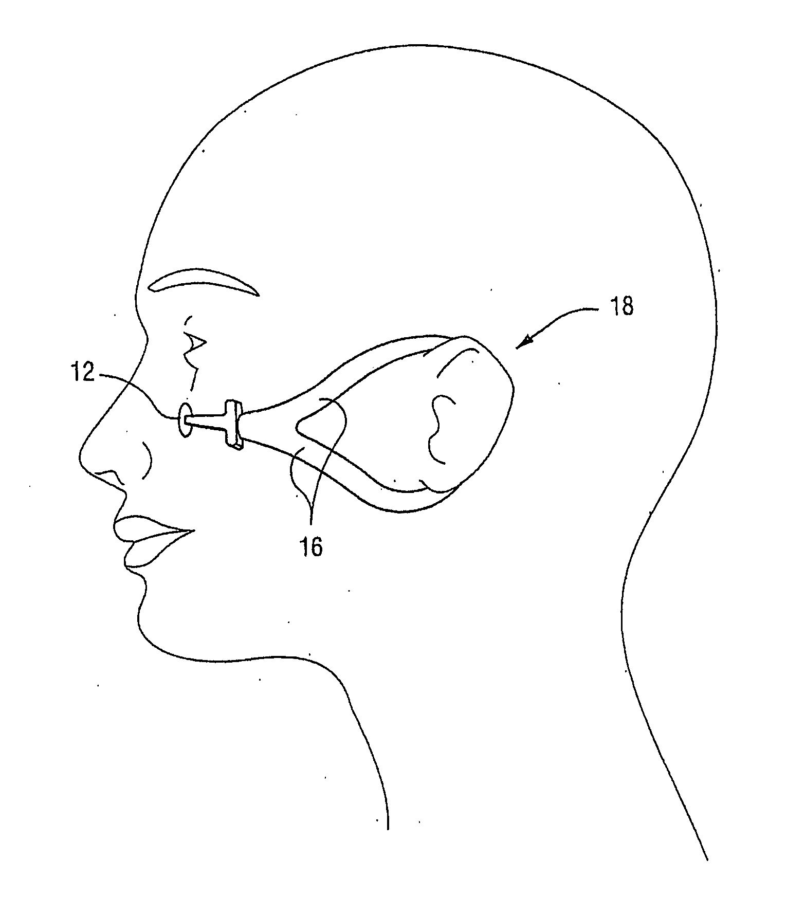
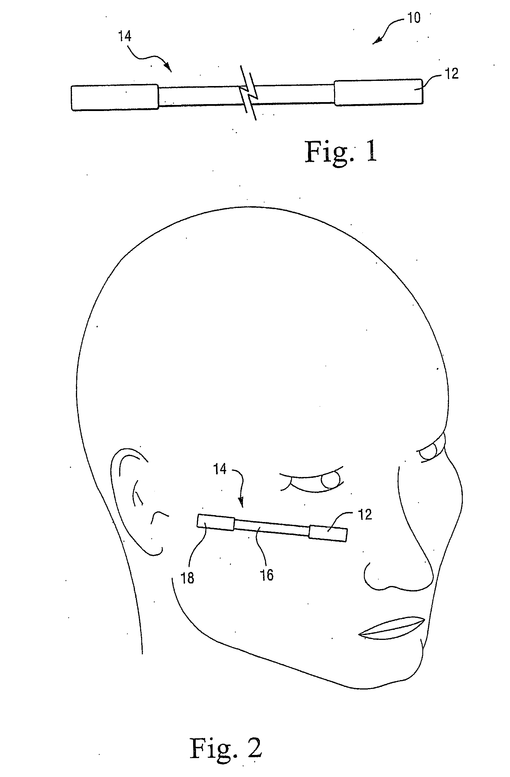
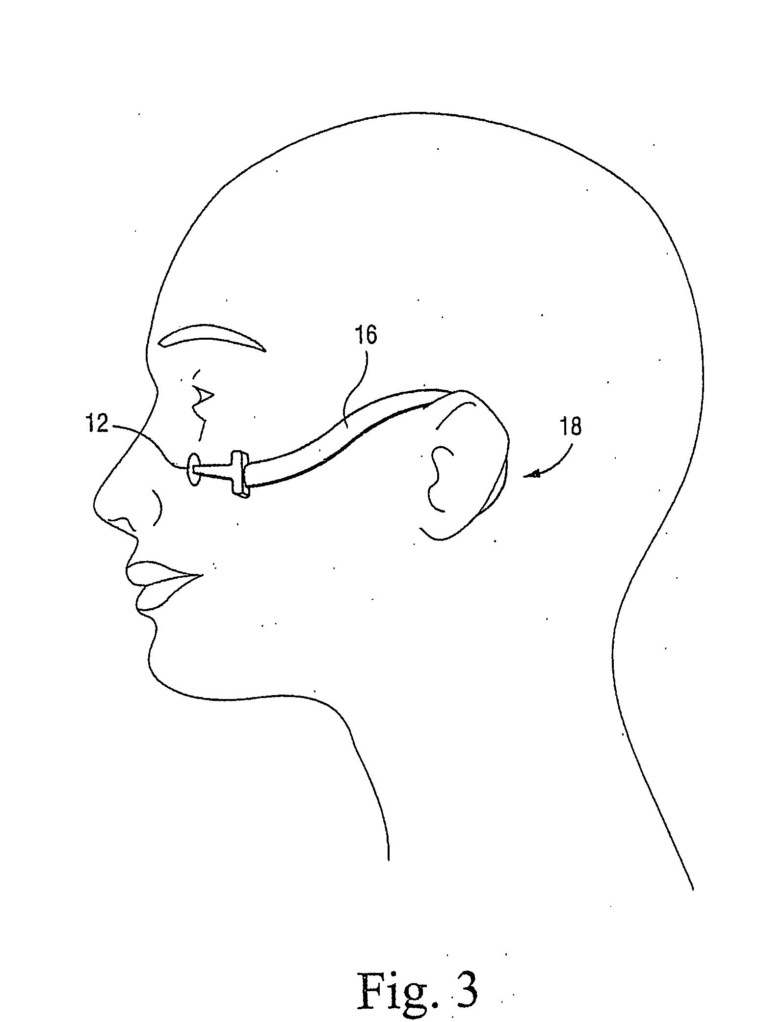
[0038]With reference to FIG. 1, in the invention, a nasal dilator 10 includes at least one contact pad 12 attachable to a facial region below the user's eye and outboard from the user's nose. More particularly, the “facial region” defined according to the invention is generally any area on the skin surface overlying the bone region known as Zygomatic bone (cheekbone region). The “facial region” also encompasses anywhere between the ear and nose, and also between the infraorbital margin (eye socket) and the line of the lips / mouth / chin. A tugging device 14 is coupled with the contact pad 12 and urges the contact pad 12 in a direction away from the user's nose. As shown in FIG. 2, in this embodiment, the tugging device includes a strip of flexible material 16 attached at a first end to the contact pad 12 and attached at a second end to a securing device 18, which is fixable relative to the user such that the flexible strip 16 is placed under tension. In the embodiment shown in FIG. 2, ...

second embodiment

[0046]With reference to FIGS. 6 and 7, the invention utilizes a U-shaped spring 20 over the bridge of the user's nose where its ends are biased, to spring outwards away from the sides of the nose (see arrows in FIG. 4). These ends may be attached to self-adhesive foam contact pads 12 that are adhered to the region outboard of the nose as previously described. The spring 20 causes the cheek regions and thus the sides of the nose to move outwards thus dilating the nasal passages.

[0047]The pads 12 may alternatively be provided with a friction quality such as textured rubber that tends to grip to the skin (e.g., soft 10 Shore A hardness silicone rubber or tacky gel). A strap 22 (shown in dashed line in FIG. 5) or other mechanical device may force the pads 12 against the face to prevent them from sliding by increasing the friction. The resultant force of the spring 20 serves to dilate the nasal passages.

[0048]Mask Version

[0049]With reference to FIG. 8, this additional friction may also b...


PUM


Abstract

A nasal dilator includes a contact pad attachable to a user's facial region below the user's eye and outboard from the user's nose. A tugging device is coupled with the contact pad and urges the contact pad in a direction away from the user's nose. With this structure, effective dilation of the nasal passages can be achieved in a comfortable manner. The dilator may also be incorporated into a CPAP mask and/or form part of an automated control system.

Description

CROSS-REFERENCES TO RELATED APPLICATIONS[0001]This application claims the benefit of U.S. Provisional Application No. 60 / 663,725, filed Mar. 22, 2005, incorporated herein by reference in its entirety.STATEMENT REGARDING FEDERALLY SPONSORED RESEARCH OR DEVELOPMENT[0002](Not Applicable)BACKGROUND OF THE INVENTION[0003]The present invention relates to a nasal dilator and, more particularly, to an outboard nasal dilator and mask-integrated nasal dilator for reducing nasal airway resistance.[0004]Nasal airway resistance causes an increased breathing effort and also promotes mouth breathing. Nasal breathing is preferable in most day-to-day circumstances because the nose provides a means to filter incoming air by trapping atmospheric pollutants in the nasal passage hairs and inner nostril mucosa (sticky) membrane before the air enters the lungs. The nasal passages also provide a means to warm and moisturize incoming air to provide breathing comfort. Increased nasal resistance can deprive p...

Claims


Application Information

Patent Timeline
Patent Type & Authority Applications(United States)
IPC IPC(8): A61M29/00A61M16/00
CPCA61F5/08A61M16/06A61M2210/0618A61M29/00A61M16/0683A61M2205/0216A61M16/0605
Inventor KWOK, PHILIP RODNEYRICHARD, RON
Owner RESMED LTD
Why Eureka
Try Eureka