Double-seat valve with a seat-cleaning function

Active Publication Date: 2015-07-30
GEA TUCHENHAGEN GMBH
View PDF2 Cites 5 Cited by
  • Summary
  • Abstract
  • Description
  • Claims
  • Application Information

AI Technical Summary

Benefits of technology

[0044]In order to avoid turbulence and stagnation pressure formation not only in the area of the aforementioned seatings of the double-seat valve, it is advantageous if all built-in parts and obstructions in the remaining leakage hollow space are foregone, if structurally possible. In this regard, one suggestion thus provides that a first adjusting rod connected with the first closing element penetrates concentrically a second adjusting rod connected with the second closing element and designed as a hollow rod, continues cantilevered through the drain bore and is permanently connected with the first closing element via at least one traverse oriented mainly radially on an end of the first closing element facing away from the second closing element. The braces and other connecting means otherwise normal in the area of the leakage hollow space are thereby avoided and displaced towards an end located relatively far from the leakage hollow space, where they can no longer have disruptive impacts on the flow guidance.
[0045]In order to reduce the flow resistance in particular in the cross-sectionally-reduced area of the drain bore, a further suggestion provides that the first adjusting rod is reduced in its cross-sec

Problems solved by technology

However, this restriction is only possible and sufficient if the annular body is always sealed sufficiently on the housing side and abuts in a sealed manner against the ventilated closing element in the necessary manner.
However, the double-seat valve according to document [2] or DE 10 2010 046 137 A1 has a big disadvantage in that the third member in the shape of a flow barrier element sealed on the housing side in connection with the other characteristic

Method used


Image

  • Double-seat valve with a seat-cleaning function
  • Double-seat valve with a seat-cleaning function
  • Double-seat valve with a seat-cleaning function

Examples


Example

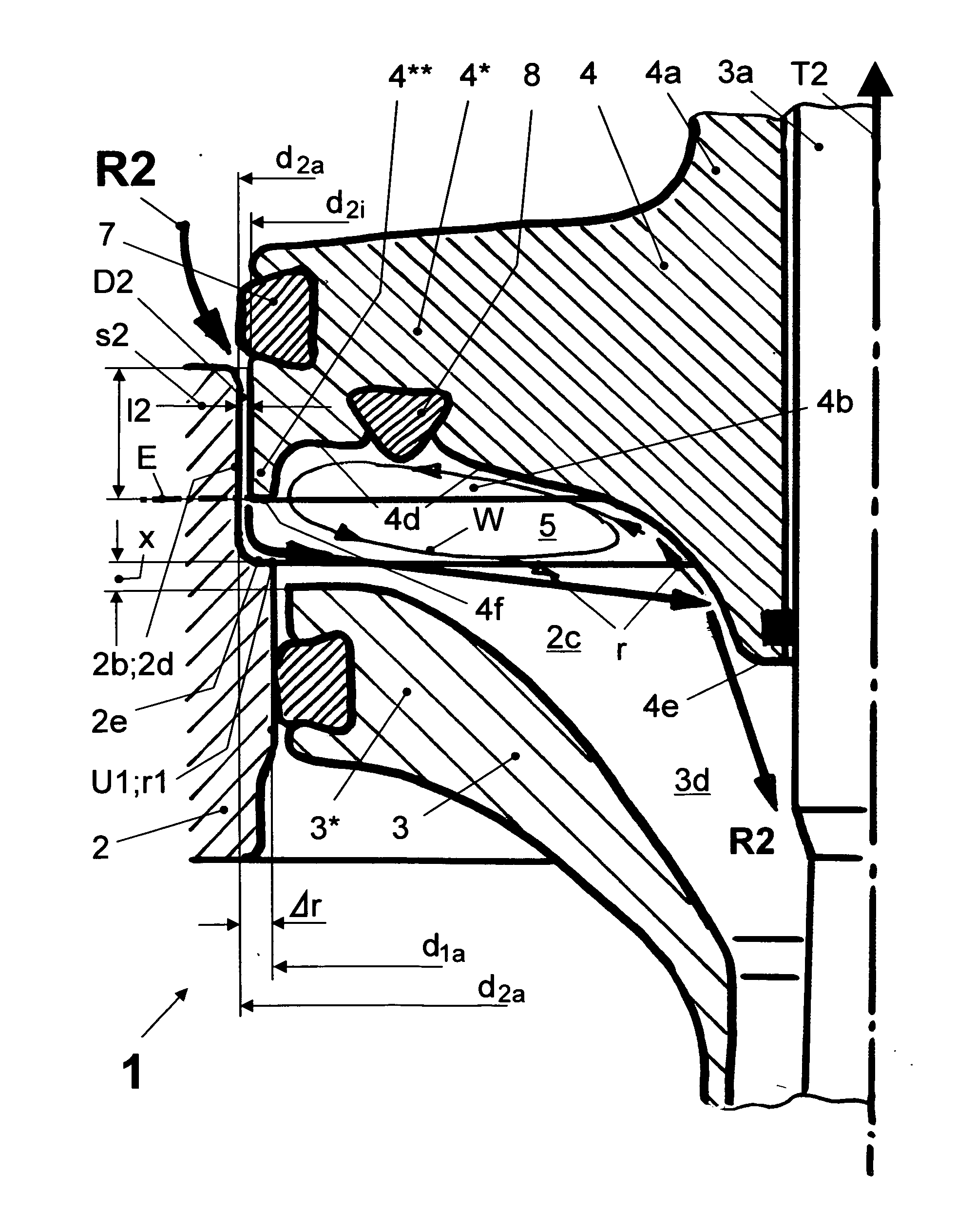
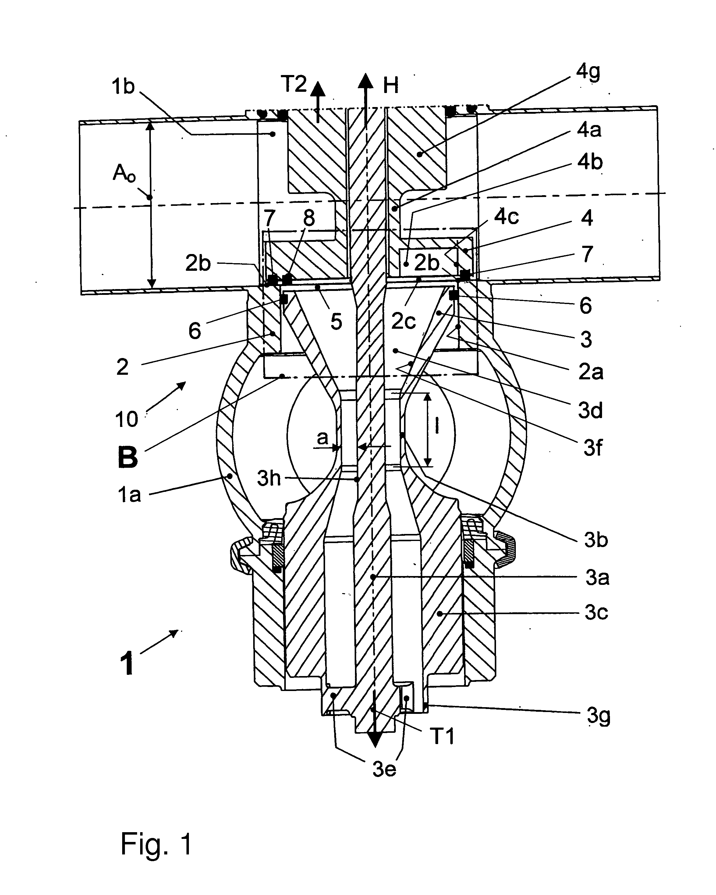
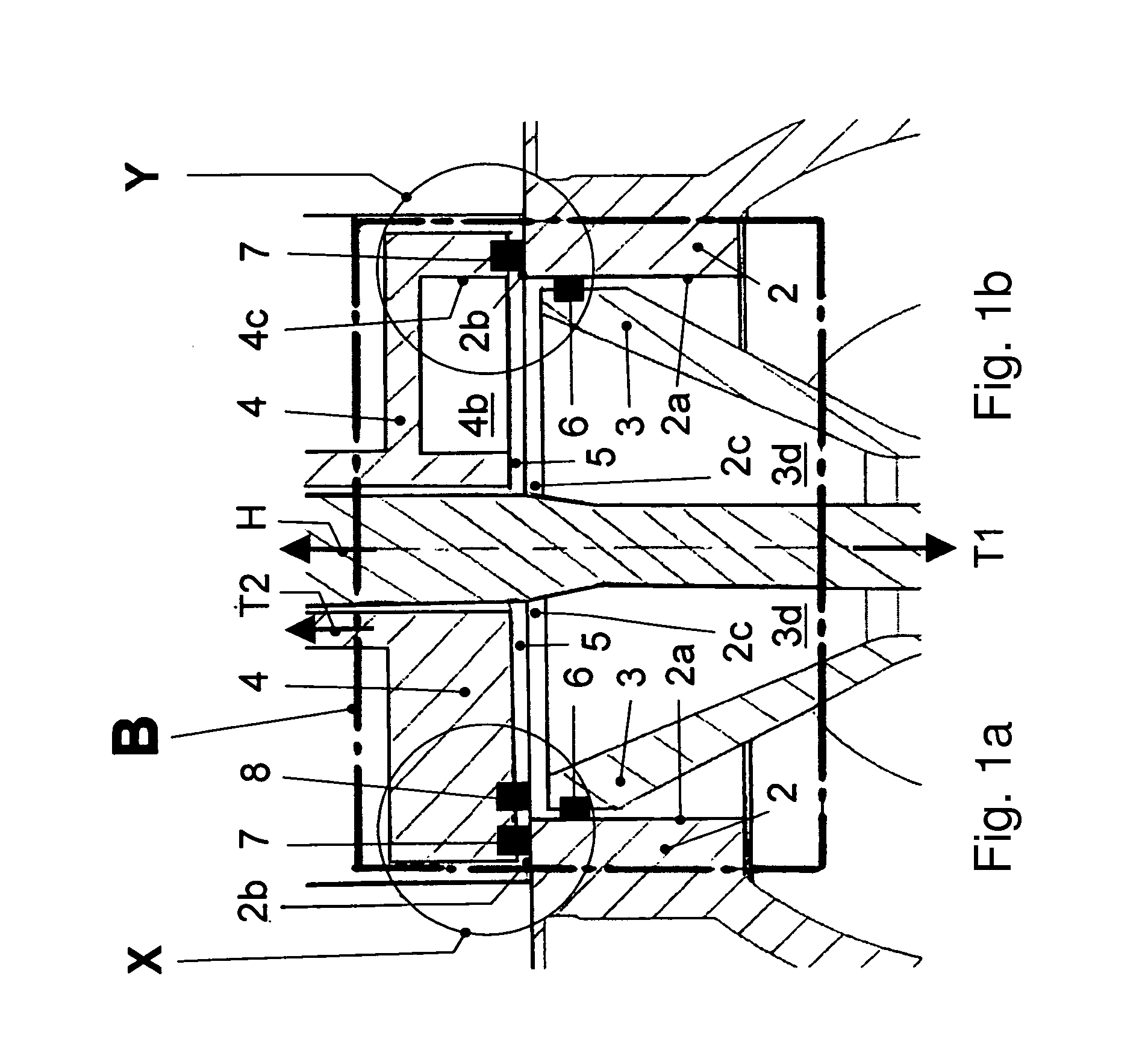
[0059]The double-seat valve 1 with a seat-cleaning function according to the invention (FIGS. 1, 1a to 1k) consists mainly of the valve housing 10 with a first and a second valve housing part 1a, 1b, the two independently moveable closing elements 3 and 4 with the respectively associated adjusting rods 3a, 4a and a seat ring 2, which establishes a connection between the valve housing parts 1a, 1b via an inside connection opening 2c.

[0060]The first closing element 3 (independently driven, active closing element) designed as a pusher piston is received in a sealing manner in the closed position of the double-seat valve 1 in a first seating 2a formed by the connection opening 2c, which is designed as a cylindrical seating (FIGS. 1, 1a to 1k, 2 to 4, 7). For this, a first seal 6 is provided in the pusher piston 3, which acts together with the first seating 2a exclusively through radial pre-tensioning (radial seal in sliding engagement). The second closing element 4 (dependently driven,...


PUM


Abstract

A double-seat valve has a seat-cleaning function and ensures that the seat-cleaning flow is conducted into and out of the leakage hollow space with as little turbulence as possible. The valve reliably prevents a pressure-increasing direct action upon the seat regions, even in the event that the cross-sectional area of the drain bore is smaller than that of the largest pipeline that can be connected to the valve. This is achieved in that a region of extension of the deflection surface that faces away from the radially outer end of the deflection surface delimits the remaining region of the opening in its entirety and opens out from the second closing element at an end-face and radially inner end of the second closing element, facing the first closing element.

Description

TECHNICAL FIELD[0001]The invention relates to a double-seat valve which has two series-arranged closing elements that are moveable relative to each other, which prevent the overflow of fluids from a valve housing part of a valve housing into another in the closed position of the double-seat valve, and which delimit a leakage hollow space between each other both in the closed as well as in the open position.BACKGROUND[0002]A double-seat valve with a seat-cleaning function is known from WO 2007 / 054131 A1 or WO 2007 / 054134 A1 and US 2009 / 0008594 A1 or respectively US 2009 / 0044874 A1 belonging to respective patent families.[0003]In the double-seat valve of the initially named patent family, the independently driven—in relation to a perpendicular normal position—lower closing element, called the first closing element below, comes to rest in a sealing manner in the course of its opening movement on the dependently driven, upper closing element, called the second closing element below, via...

Claims


Application Information

Patent Timeline
IPC IPC(8): F16K1/44
CPCF16K1/446Y10T137/88038
Inventor BURMESTER, JENSSCHULZ, ARNESUDEL, MATTHIASTOLLE, BASTIAN
Owner GEA TUCHENHAGEN GMBH
Why Eureka
Try Eureka