Ship

a technology for ships and hulls, applied in the field of ships, can solve the problems of affecting and affecting the safety of sailing in relative large stern quartering or following waves, so as to reduce the length of ships, improve the behavior of ships in heavy seas, and reduce the wet surface and flow resistance

a technology for ships and hulls, applied in the field of ships, can solve the problems of affecting and affecting the safety of sailing in relative large stern quartering or following waves, so as to reduce the length of ships, improve the behavior of ships in heavy seas, and reduce the wet surface and flow resistance

US20090114137A1Inactive Publication Date: 2009-05-07TECH UNIV DELFT

Image

  • Ship
  • Ship
  • Ship

Examples


second embodiment

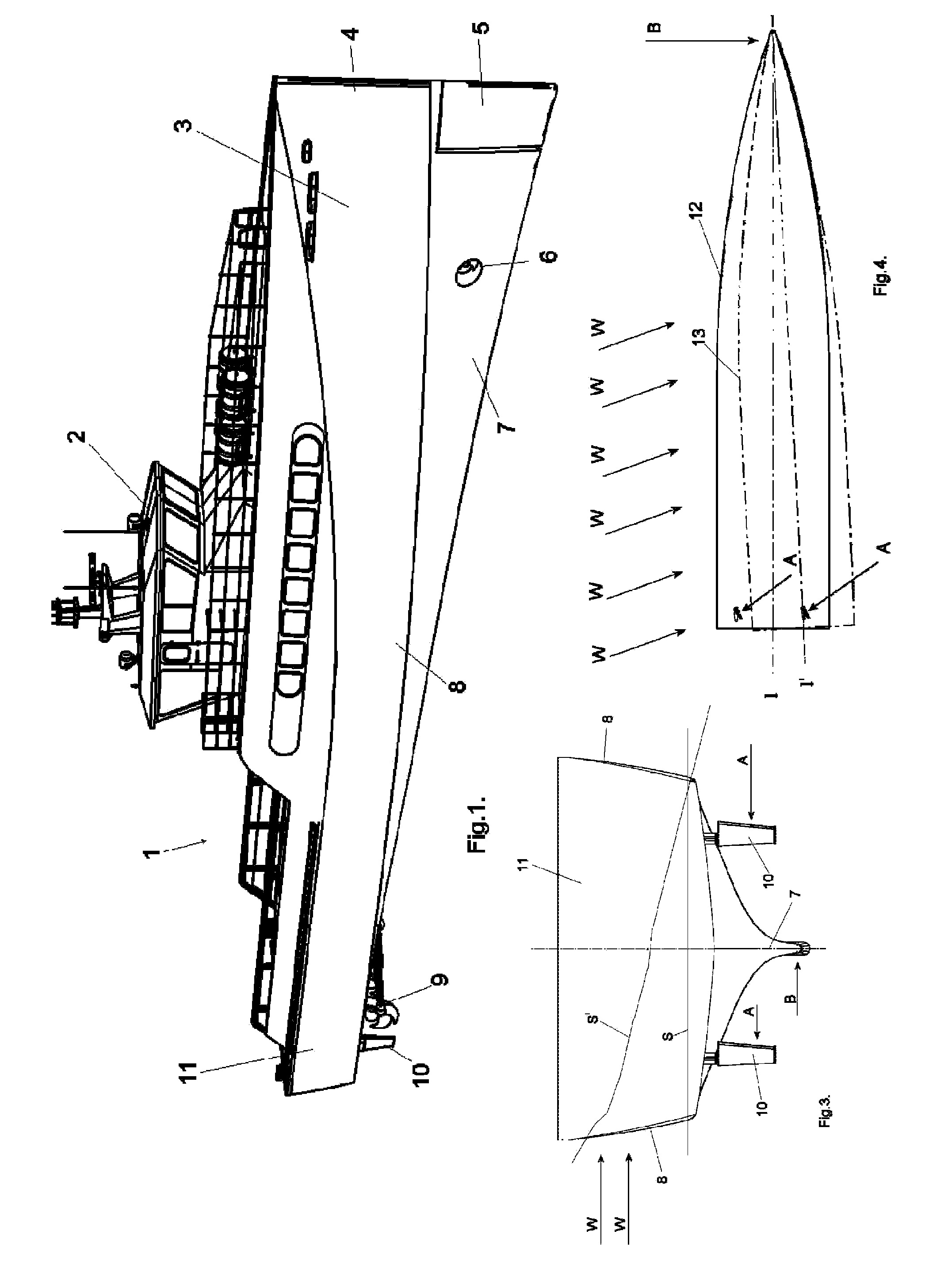
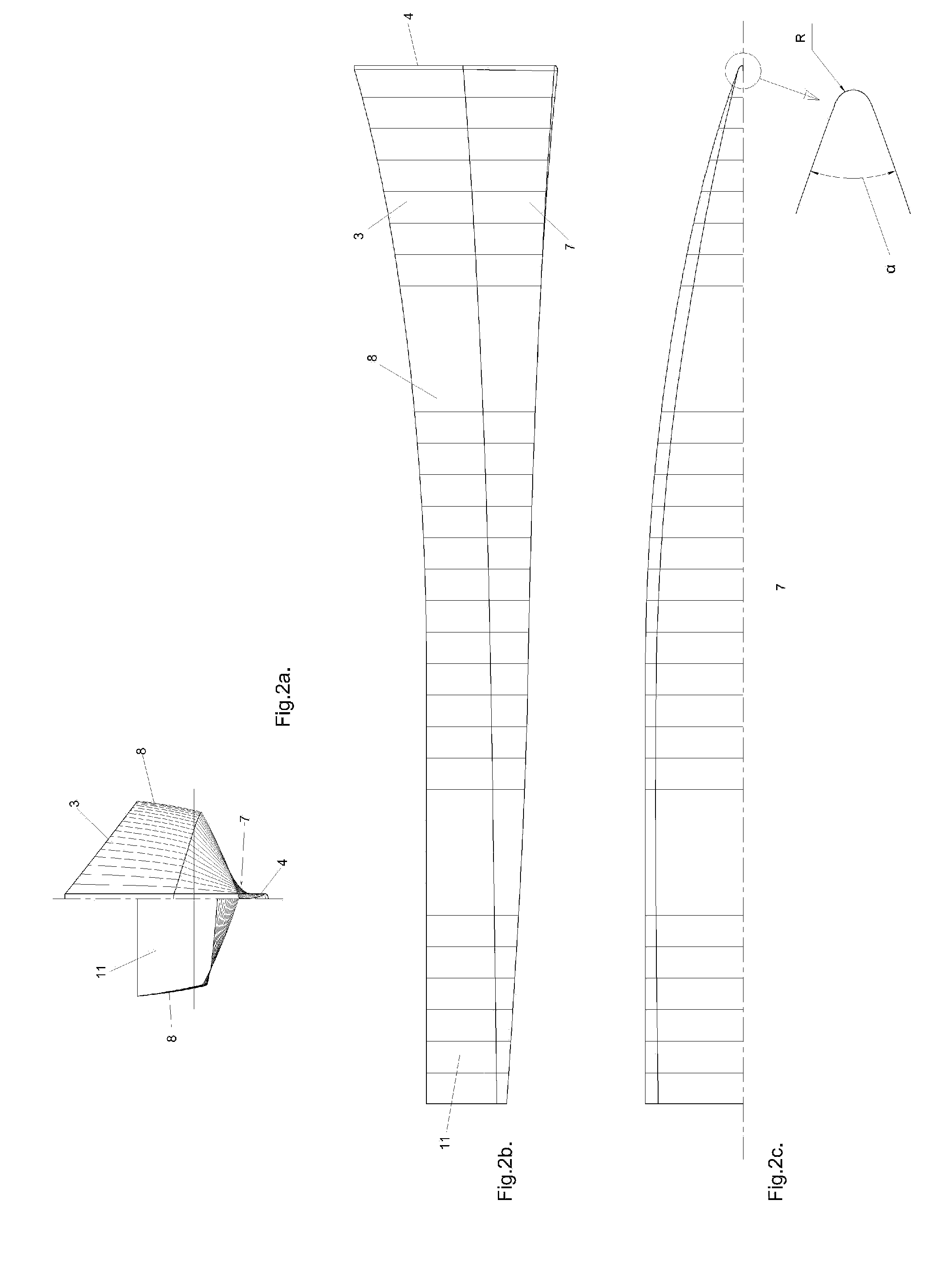
[0036]FIGS. 6a and 6b show the bow 4 of the ship 1. Instead of a conventional rudder located in the bow 4 the lateral forces B for steering the ship 1 are now generated by the flow F along a side flap 16. On each side of the bow 4 there is a side flap 16, these side flaps 16 rotate around a more or less vertical axis 17, which axis 17 is supported at the lowest part of the bow 4 by a support 15. When not activated the side flaps 16 follow the contour of the foreship 3 and are positioned against a brace 18. For moving the side flaps 16 so that they can generate an adjustable lateral force B there is a mechanism 19. This mechanism 19 can be formed by two hinged levers connected to each other and respectively the foreship 3 and the side flap 16. The hinge connecting these levers can be moved in vertical direction by a hydraulic cylinder (not shown). This hydraulic cylinder can be located above the water level and is con-trolled such that either the one or the other side flap 16 is move...

third embodiment

[0037]FIGS. 7a and 7b show the bow 4 of ship 1. A submerged part of the bow 4 now consists of a rotor 20 that can rotate around a more or less vertical rotation axis 21. For driving the rotor 20 there is a drive 23 that drives the rotor 20 via a transmission 22. The drive 23 can be electric or hydraulic and can be located above the water level. During rotation the rotor 20 acts as a so called Magnus rotor and generates asymmetric pressure fields at the different sides of the bow 4 so that a lateral force B is the result. By changing the speed of rotation of the rotor 20 the magnitude of the lateral force B can be adjusted.


PUM


Abstract

A ship for use at high speed and / or heavy seas having a single long and slender hull, a sharp bow and the aft end of the hull has a flat or slightly V-shaped bottom with at least one aft rudder, and at least one propeller or water jet for propulsion whereby the foreship has a draught that is equal or more than the draught of the aft end. The bow has a control surface that converts the water flow along the forward moving ship into an adjustable lateral force.

Description

CROSS-REFERENCE TO RELATED APPLICATIONS[0001]The present application is a continuation of pending International patent application PCT / EP2007 / 056613 filed on Jun. 30, 2007, which designates the United States and claims priority from European patent application 06116486.9 filed on Jun. 30, 2006, the content of which is incorporated herein by reference.FIELD OF THE INVENTION[0002]The invention concerns a ship for use at high speed and / or heavy seas having a single long and slender hull, a bow and the aft end of the hull has a flat or slightly V-shaped bottom with at least one aft rudder, one or more propellers and / or water jets as propulsions means whereby the foreship has a draught that is equal or more than the draught of the aft end characterized in that the bow has a control surface that converts the water flow along the forward moving ship into an adjustable lateral force.BACKGROUND OF THE INVENTION[0003]For most ships of such design the condition of sailing in relative large ste...

Claims


Application Information

Patent Timeline
07 May 2009
Publication
US20090114137A1
IPC
B63H25/44; B63H25/06
CPC
B63B1/06; B63B2001/066; Y02T70/126; B63H25/44; B63H2025/063; B63H25/38; B63B39/06; Y02T70/10
Inventors
KEUNING, JAN ALEXANDER