Apparatus and method for processing molten glass

a technology of apparatus and glass, applied in glass making apparatus, glass rolling apparatus, manufacturing tools, etc., can solve the problems of increasing the cost, increasing the cost, and expensive batch process requiring multiple steps, so as to reduce the flow impedance and increase the diameter of the condui

Active Publication Date: 2016-06-30
CORNING INC
View PDF4 Cites 4 Cited by
  • Summary
  • Abstract
  • Description
  • Claims
  • Application Information

AI Technical Summary

Benefits of technology

[0007]To meet the space requirements for a glass forming apparatus comprising one or more forming bodies a delivery vessel that delivers molten glass to a trough of the one or more forming bodies may need to be located a significant distance from the forming body. This can results in a delivery conduit that may impede the flow of molten glass to the respective forming body, placing restrictions on the maximum flow rate of molten glass through the conduit and hence to the forming body. On the other hand, simply increasing the diameter of the conduit to reduce the flow impedance can create a sump region within the conduit, where the conduit bottom is lower than the trough of the forming body, creating the potential for molten glass to cease flowing and become stagnant. Accordingly, embodiments disclosed herein described composite delivery conduits comprising non-circular cross sections that enable an enlarged cross sectional flow area but wherein an inside bottom surface of the delivery conduit does not extend below a bottom surface of the forming body conduit and an upper inside surface of the delivery conduit does not extend above a top of the trough inlet.

Problems solved by technology

However, ion-exchanging does not readily lend itself to an in-line process, and therefore becomes an expensive batch process requiring multiple steps.
Moreover, the chemicals used in the ion exchange process must be properly handled to comply with environmental constraints, further adding to the expense.
Applications that would otherwise benefit from strengthened glass, such as glass cover plates for household appliances, e.g. refrigerators, may not warrant the expense of ion-exchanged glass.
This can results in a delivery conduit that may impede the flow of molten glass to the respective forming body, placing restrictions on the maximum flow rate of molten glass through the conduit and hence to the forming body.

Method used


Image

  • Apparatus and method for processing molten glass
  • Apparatus and method for processing molten glass
  • Apparatus and method for processing molten glass

Examples


Embodiment Construction

[0029]Reference will now be made in detail to embodiments disclosed herein, examples of which are illustrated in the accompanying drawings. Whenever possible, the same reference numerals will be used throughout the drawings to refer to the same or like parts.

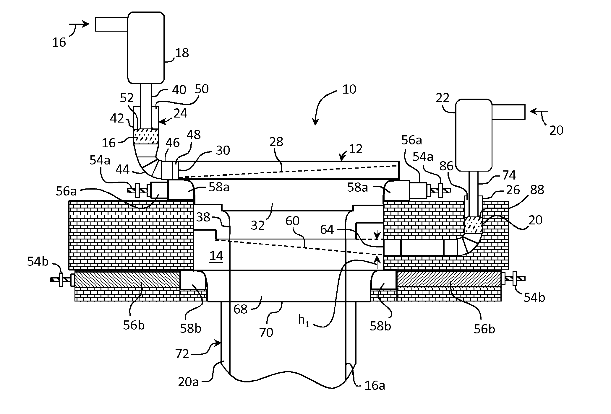
[0030]FIG. 1 illustrates an example glass forming apparatus comprising two forming bodies, wherein one forming body is positioned vertically below the other forming body. Each forming body is supplied with molten glass from a separate delivery vessel and includes separate devices for supporting and longitudinally compressing the respective forming body to prevent sagging when operating for extended periods at high temperature. Because this equipment is located at both ends of each forming body, and the vertically aligned placement of the forming bodies consumes valuable space around each forming body, the delivery vessel supplying molten glass to the lower forming body is displaced farther from the lower forming body than the de...


PUM

PropertyMeasurementUnit
viscosityaaaaaaaaaa
widthaaaaaaaaaa
viscosityaaaaaaaaaa

Abstract

A glass forming apparatus for processing molten glass is disclosed comprising a delivery vessel for delivery molten glass to a forming body through a delivery conduit, the delivery conduit comprising a first portion have a circular cross-sectional shape, a second portion comprising a circular cross-sectional shape and a third portion comprising a non-circular cross-sectional shape. The delivery conduit further comprises a first transition portion coupling the second portion to the third portion, and a second transition portion coupling the third portion to an inlet of a trough in a forming body. Neither an inside bottom surface of the third portion, nor an inside bottom surface of the second transition portion, is lower than a bottom surface of the forming body trough. A method of processing molten glass is also described.

Description

PRIORITY[0001]This application claims the benefit of priority under 35 U.S.C. §119 of U.S. Provisional Application Ser. No. 61 / 868,835 filed on Aug. 22, 2013, the content of which is relied upon and incorporated herein by reference in its entirety.BACKGROUND[0002]1. Field[0003]The present disclosure relates generally to an apparatus and method for the processing of molten glass, and more particularly an apparatus and method for conveying molten glass from a delivery vessel to a forming body.[0004]2. Technical Background[0005]The fusion glass making process is known for producing high quality glass sheets of extraordinary thinness without grinding or polishing to further thin the as-drawn glass. The process in its simplest form comprises flowing molten glass over two opposing and converging sides of a forming body, wherein the separate flows of glass meet at a bottom edge of the forming body to form a glass ribbon. The glass ribbon cools to an elastic state, after which the ribbon ca...

Claims


Application Information

Patent Timeline
Patent Type & Authority Applications(United States)
IPC IPC(8): C03B7/02C03B7/07C03B17/06C03B17/02
CPCC03B7/02C03B17/064C03B7/07C03B17/02
Inventor KERSTING, JOHN JERRY
Owner CORNING INC
Why Eureka
Try Eureka