Expandable medical access device

a medical access device and expandable technology, applied in the field of expandable medical access devices, can solve the problems of increasing patient discomfort and poor cosmetics, affecting the quality of life of patients, so as to achieve the effect of increasing the diameter of the tubular member

Active Publication Date: 2010-04-20
ONSET MEDICAL CORP
View PDF43 Cites 142 Cited by
  • Summary
  • Abstract
  • Description
  • Claims
  • Application Information

AI Technical Summary

Benefits of technology

[0013]Accordingly, one embodiment of the present invention relates to an access apparatus for providing minimally invasive surgical access that comprises a tubular member formed from a rolled sheet of thin walled material. The thin walled material includes an inner surface, an outer surface, an inner edge and an outer edge. A first component is coupled an inner portion of the thin walled material and a second component coupled to an outer portion of the thin walled material. An actuation mechanism is configured such that rotation of the first component with respect to the second component unwinds the rolled sheet of thin walled material to increase the diameter of the tubular member.
[0015]In another embodiment of the present invention, an access apparatus comprises a sheath that is fabricated from a thin walled sheet of material. The piece of material is rolled tightly to create a small diameter configuration that is inserted into the patient. A control member is coupled to the sheath near an innermost edge of the sheath. The control member extends substantially to the proximal most portion of the sheath. By rotating the control member, the operator causes the thin wall sheet of metal or plastic to unfurl into a larger or smaller diameter, depending on the direction of rotation. A mechanical lock at the proximal end of the sheath permits the control member to be selectively constrained to prevent rotation and thus lock the sheath diameter in place. In a modified embodiment, the sheath may be supplied with an internal obturator, a proximal seal for instruments, and / or insulation to prevent or minimize the escape of energy, fluids, or contaminants from the interior of the sheath to surrounding tissue.
[0016]In yet another embodiment, a laparoscopic version of the sheath is used to create a dome over the surgical site. The dome is created at the distal end of the sheath and is preferably radially dilated separately from the sheath. The dome is, in this embodiment, a separate winding of material with a separate control member that passes through or alongside the sheath. An elastomeric, expandable, or unfurling material connecting the delivery sheath to the dome provides a seal at the proximal end of the dome to isolate tissues captured within the dome from surrounding tissues. The exterior of the device would gently move uninvolved organs and tissue out of the surgeon's area of interest. The interior of the dome would provide adequate space for visualization, sewing and clipping for hemostasis as well as for tissue re-approximation. Infusion and removal of fluids are preferably available to maintain a clear surgical field.

Problems solved by technology

While large incisions may heal as quickly as small ones, they are a source of extended patient discomfort and poor cosmetics along with expensive recovery periods, both in and out of the hospital.
However, minimally invasive access systems for surgical procedures that do not invade body cavities, such as the abdomen or thorax may not be suited for traditional laparoscopic visualization.
Surgical exposure is limited by the accurate placement of the cannula, location of pathology and diameter of the cannula.
Should the operative procedure require expansion with incision and traditional retraction applied, the recovery course may be longer and costs higher than if the minimally invasive approach was used.
Surgical incision sites must enlarged carefully, however, because most operators are reluctant to expand surgical exposure at the risk of losing the anatomic landmark.

Method used


Image

  • Expandable medical access device
  • Expandable medical access device
  • Expandable medical access device

Examples


Embodiment Construction

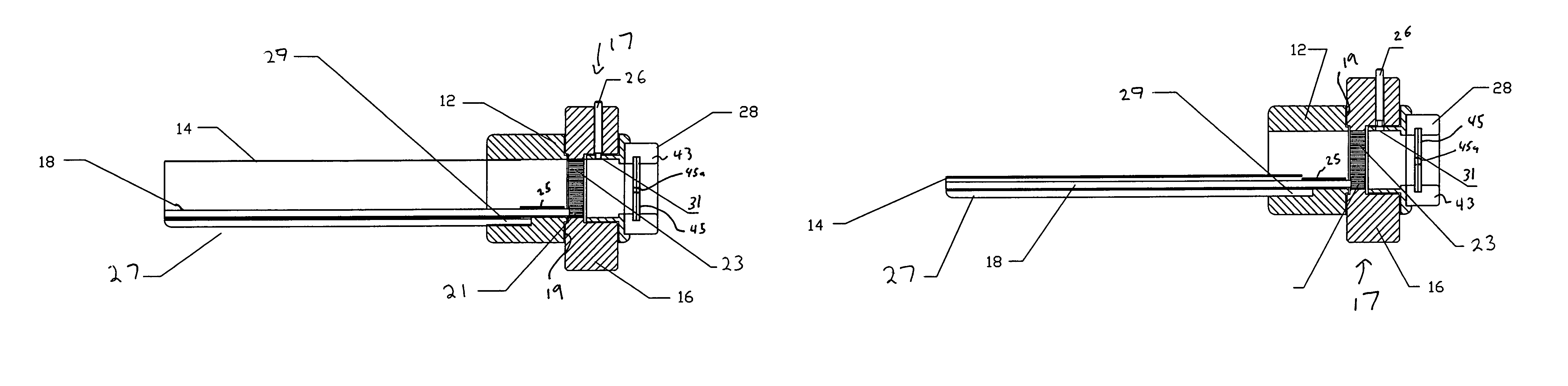
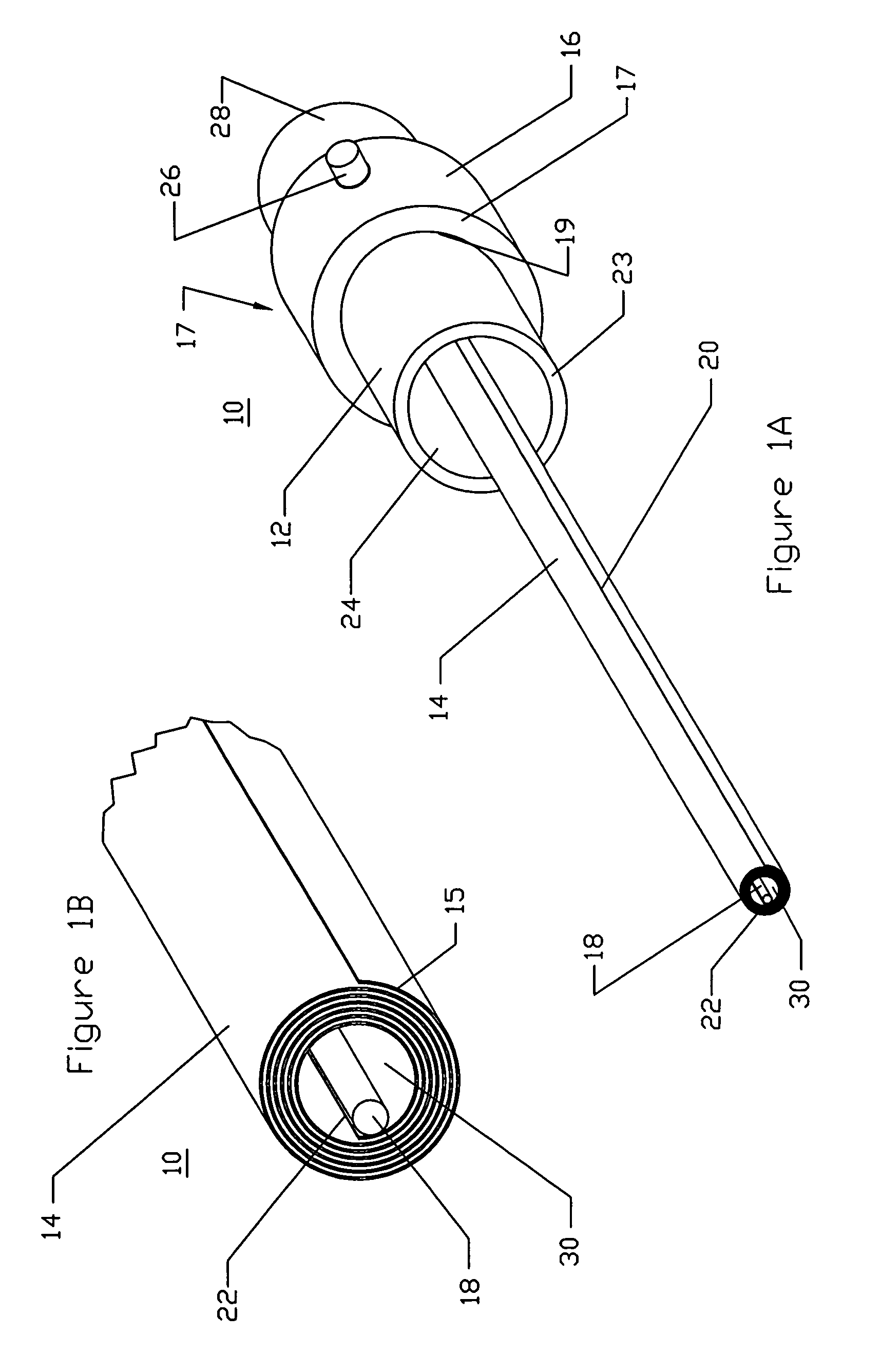
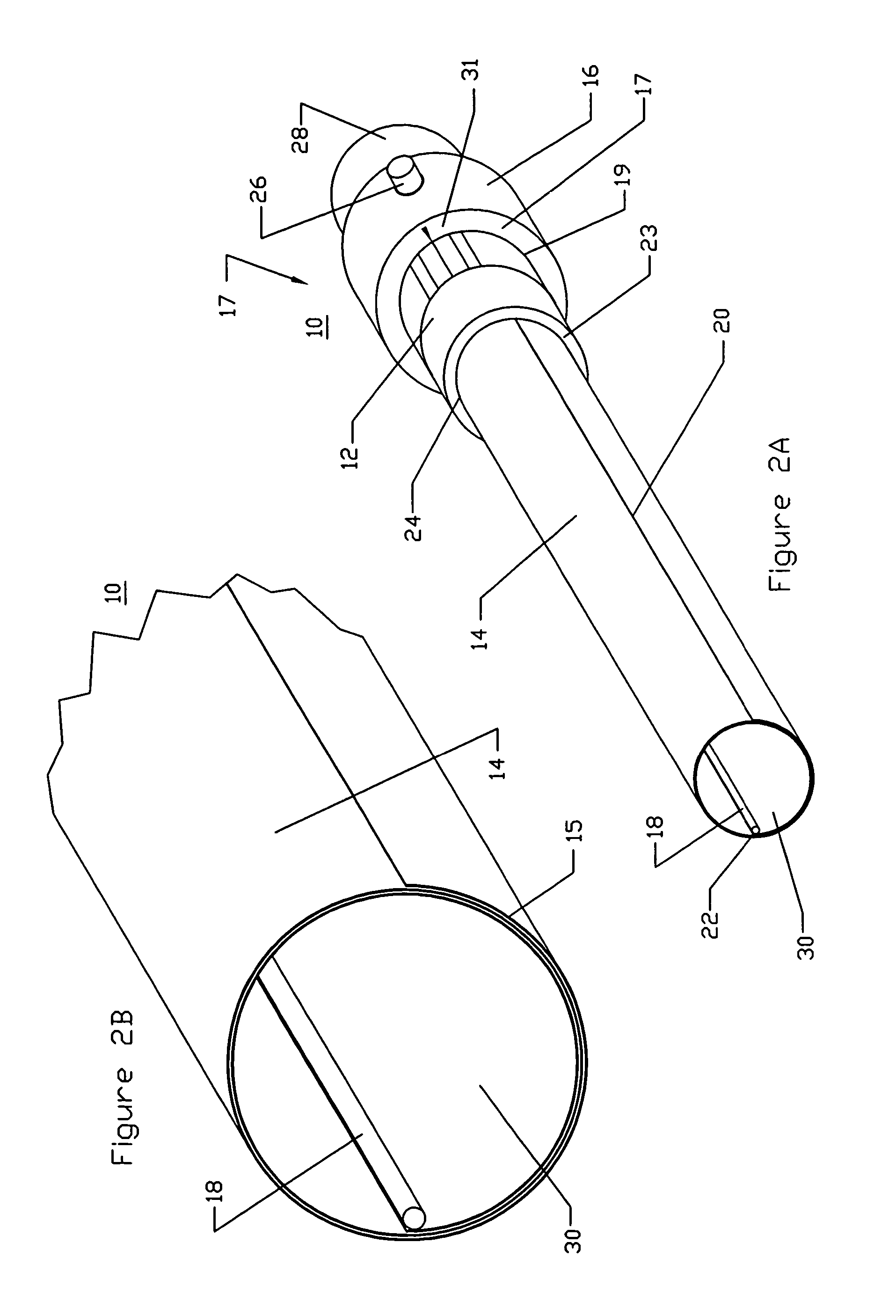
[0035]FIG. 1A illustrates a side perspective view of an exemplary embodiment of an access system 10 in its radially compressed configuration. FIG. 2A is a side perspective view of the access system 10 of FIG. 1A in an expanded or enlarged profile configuration. The system 10 comprises a proximal hub 12 and a tubular shaped sheath 14, which is formed from a thin walled material 15 that is wound about its longitudinal axis. With reference to FIGS. 10A and 10B, in the illustrated embodiment, the thin walled material comprises a generally longitudinally oriented outer edge 20, a longitudinally oriented inner edge 22, a proximal edge 19, a distal edge 21, a periphery surface 25 and a lumen facing surface 27. When wound about its longitudinal axis, the thin walled material 15 defines a central lumen 30 (see FIGS. 1A and 2A). In the illustrated embodiment, the hub 12 comprises a tubular member 23, which forms an inner lumen 24.

[0036]In the compressed configuration (FIG. 1A), the sheath 14 ...


PUM


Abstract

An access device comprises a thin-walled sheath that is insertable into a patient through a small surgically created incision. The incision may be created using a cutdown or a percutaneous method such as that known as the Seldinger technique. Once inserted and advanced to the target surgical site, the sheath is selectively, and controllably, expanded to a desired diameter. The thin wall of the sheath is fabricated from a rectangular piece of material such as metal or plastic with two cut edges. The rectangular piece of metal or plastic is rolled tightly to create the small diameter configuration that is inserted into the patient. A cam or control member is affixed to the innermost edge of the rectangular piece of metal or plastic. The control member extends to the proximal most portion of the sheath. By rotating the control member, the operator causes the thin wall piece of rolled material to unfurl into a larger or smaller diameter, depending on the direction of rotation. A mechanical lock at the distal end of the sheath permits the control member to be selectively constrained from rotation and thus lock the sheath diameter in place.

Description

[0001]This application claims the priority benefit under 35 U.S.C. § 119(e) of Provisional Application 60 / 554,338 filed Mar. 18, 2004.BACKGROUND OF THE INVENTION[0002]1. Field of the Invention[0003]This invention relates to medical access devices and, in particular, to expandable medical access devices for providing minimally invasive surgical access for various surgical procedures.[0004]2. Description of the Related Art[0005]A wide variety of diagnostic or therapeutic procedures involve the introduction of a device through a natural or artificially created access pathway. As such, minimally invasive access systems have been developed to generate such pathways. A general objective of these access systems is to minimize the cross-sectional area of the puncture, while maximizing the available space for the diagnostic or therapeutic instrument. Procedures that utilize access systems include, among others, a wide variety of laprascopic diagnostic and therapeutic interventional procedure...

Claims


Application Information

Patent Timeline
Patent Type & Authority Patents(United States)
IPC IPC(8): A61M29/00A61B17/02A61B17/34A61B17/44
CPCA61B17/3439A61B17/0218
Inventor KICK, GEORGE F.LENKER, JAYTCHULLUIAN, ONNIK
Owner ONSET MEDICAL CORP
Why Eureka
Try Eureka