Balloon expandable crush-recoverable stent device
- Summary
- Abstract
- Description
- Claims
- Application Information
AI Technical Summary
Benefits of technology
Problems solved by technology
Method used
Image
Examples
embodiment 300
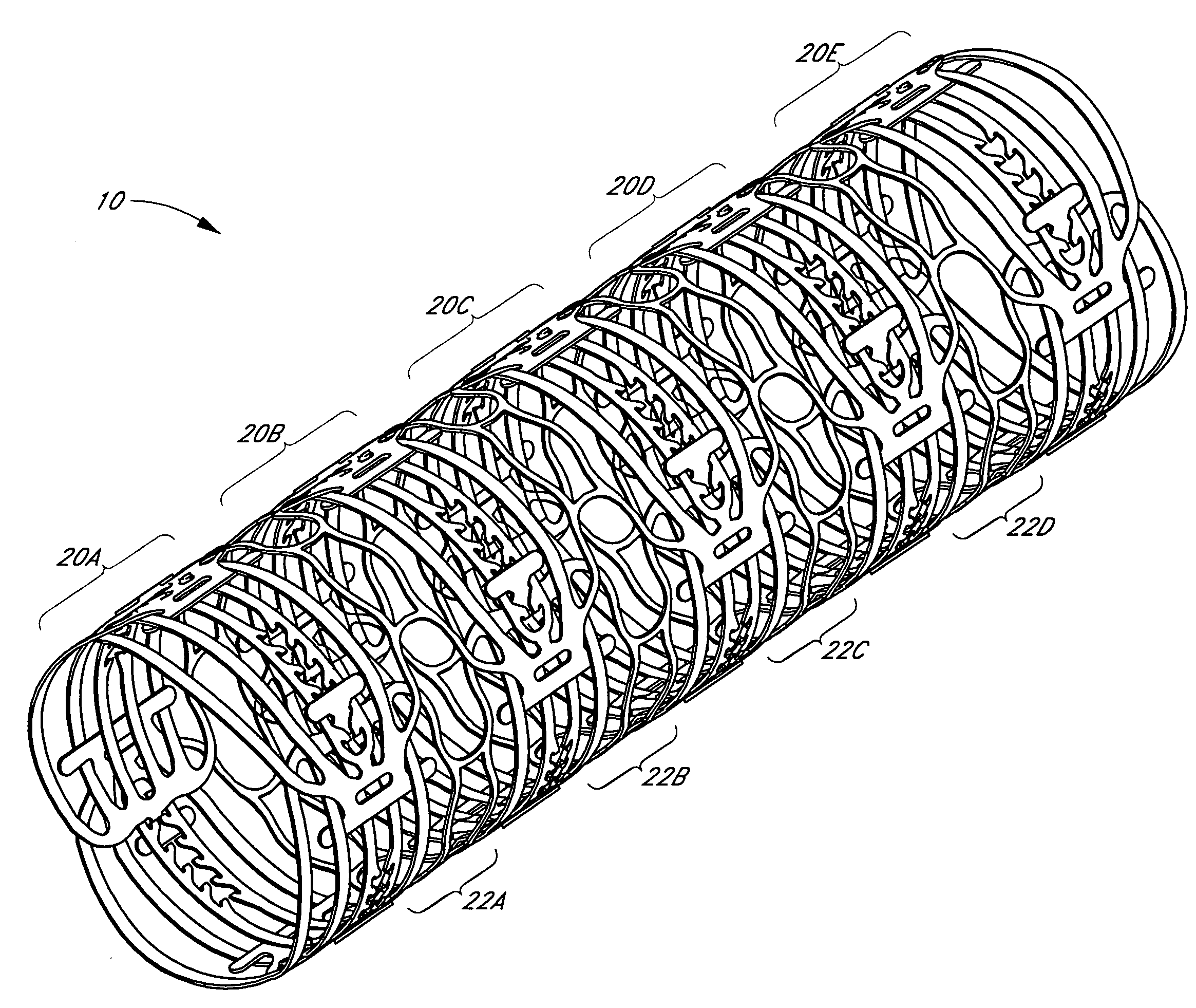
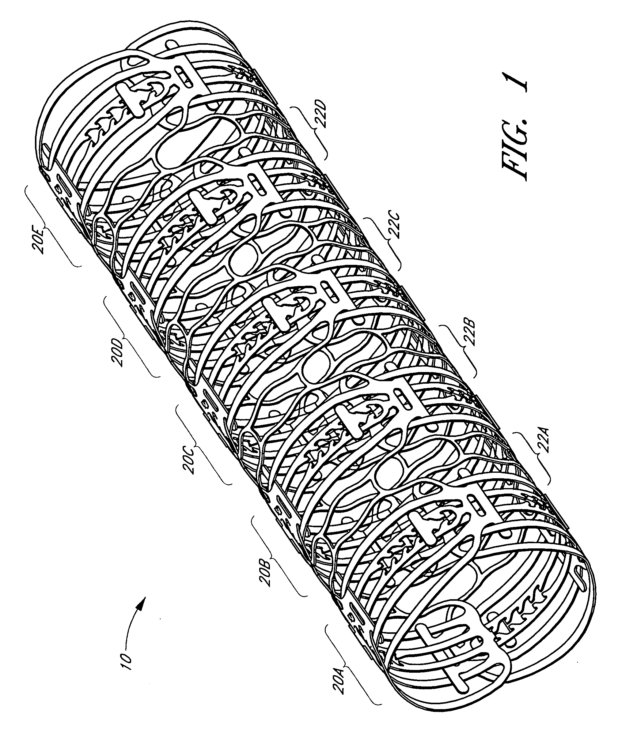
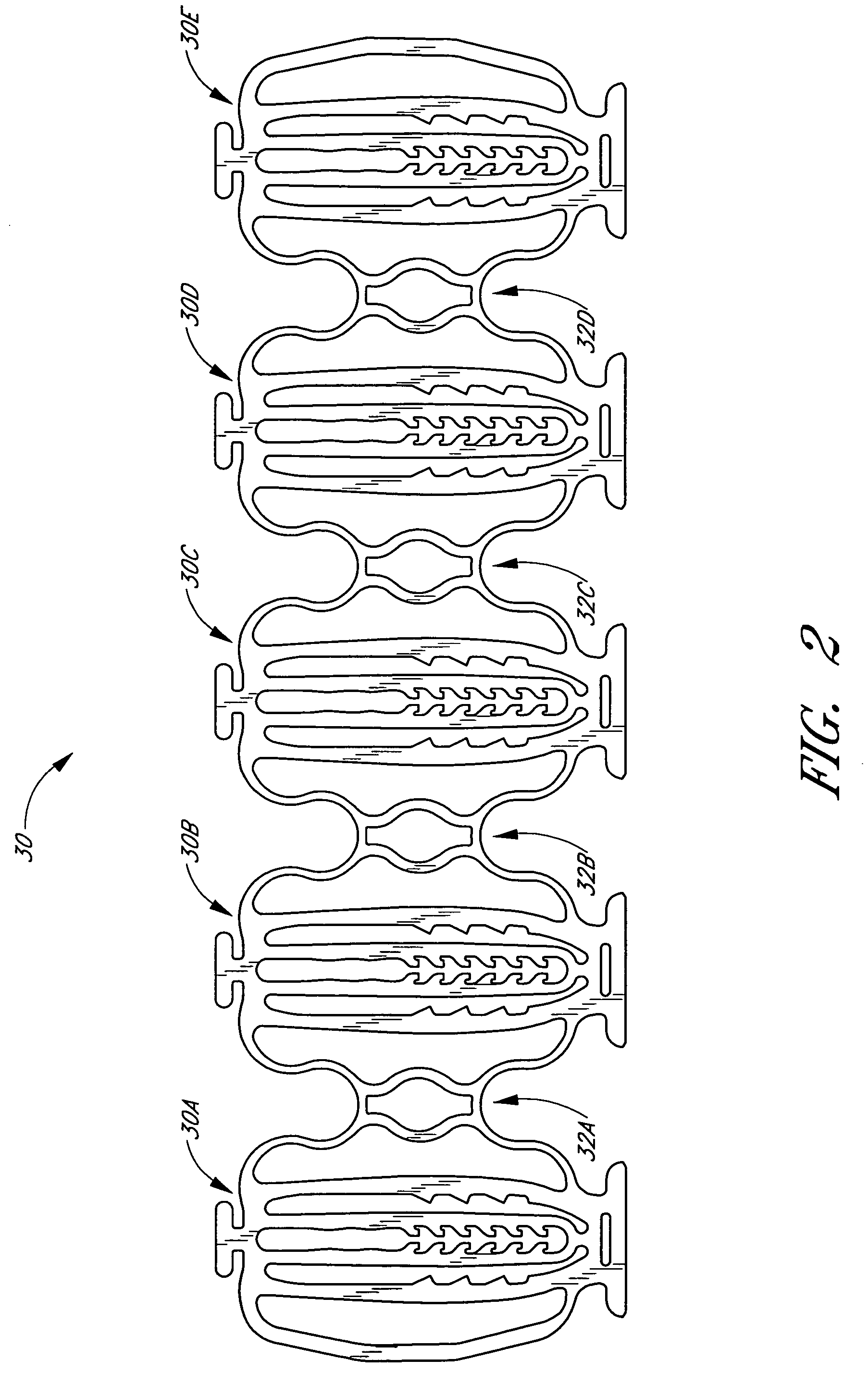
[0116] In yet another alternative embodiment of a balloon expandable crush-recoverable stent, it will be appreciated that deflectable teeth may be used, rather than deflectable members, to provide the stent with mono-directional expansion. For example, FIG. 12 illustrates a portion of another stent embodiment 300 wherein two radial elements 300(1), 300(2) are slidably interconnected. Each radial element is provided with a longitudinal member 308 having a plurality of deflectable teeth 306. Similar radial elements may be coupled via flexible linkage elements 310, 312 to provide a stent having a desired axial length. In this embodiment, locking tabs 302, 304 are configured to ride along the sides of the deflectable teeth 306. Each of the teeth is sufficiently flexible such that the teeth may deform inward toward the longitudinal member 308 (i.e., within the plane of the radial element) for allowing the locking tabs 302, 304 to pass in one direction. However, due to the angle of the te...
embodiment 320
[0117] With reference now to FIG. 13, a portion of another preferred stent embodiment 320 is illustrated wherein radial elements 320(1), 320(2) are slidably interconnected. Similar to the embodiment just described, each radial element is provided with a single longitudinal member 328 having a plurality of deflectable teeth 326. However, in this embodiment, each of the teeth is angled upward and is configured to deflect downward (i.e., in a radial direction), rather than inward toward the longitudinal member as discussed with respect to FIG. 12. As the locking tabs 322, 324 ride along the deflectable teeth 326, the teeth are caused to deflect downward for allowing the tabs 322, 324 to pass over the teeth 326 during deployment. However, due to the angle of the teeth, the locking tabs may only move in one direction. More particularly, if a compressive force pushes the radial elements 320(1), 320(2) back toward the collapsed condition, the locking tabs 322, 324 will abut against the tee...
embodiment 340
[0118] With reference now to FIG. 15, a portion of another stent embodiment 340 is illustrated wherein radial elements 340(1), 340(2) are slidably interconnected. Each radial element is provided with an outer surface formed, at least in part, with a series of serrations or ridges. More particularly, the surfaces comprise a series of valleys 344 and ridges 346. In the illustrated configuration, a locking tab 342 of radial element 340(2) slides along the surface of radial element 340(1). The locking tab 342 is formed with a thin neck portion 350 and a wider head portion 352. The neck portion 350 is configured for allowing the head 352 to deflect outward in a radial direction. The shape of the valleys 344 and ridges 346 allows the head 352 of the locking tab 342 to ratchet along the surface of the adjacent element in only one direction, thereby providing a locking means to maintain the stent in the expanded condition. Although the ridges and valleys are only necessary along the region ...
PUM
 Abstract
Description
Claims
Application Information
 - R&D
- Intellectual Property
- Life Sciences
- Materials
- Tech Scout
- Unparalleled Data Quality
- Higher Quality Content
- 60% Fewer Hallucinations
Browse by: Latest US Patents, China's latest patents, Technical Efficacy Thesaurus, Application Domain, Technology Topic, Popular Technical Reports.
© 2025 PatSnap. All rights reserved.Legal|Privacy policy|Modern Slavery Act Transparency Statement|Sitemap|About US| Contact US: help@patsnap.com


