Anti-separation dry sand silo and method

An anti-segregation and dry sand technology, applied in the field of dry sand silo, can solve the problems affecting the quality of the finished dry-mixed mortar, unclean discharge of the dry sand silo outlet, and speeding up the aging speed of the equipment, so as to improve the quality of the finished mortar, The effect of high reliability and avoiding unsmooth falling

Inactive Publication Date: 2014-01-22
徐州沃土资产管理有限公司
View PDF7 Cites 5 Cited by
  • Summary
  • Abstract
  • Description
  • Claims
  • Application Information

AI Technical Summary

Problems solved by technology

[0002] At present, the storage warehouse for storing dry sand in the dry-mixed mortar station mainly adopts a vertical drop structure, so that the dried dry sand directly falls into the warehouse. Due to the large internal drop of the warehouse and different particle sizes ( 0-5mm) dry sand has different specific gravity, and the speed of free fall is different. During storage and accumulation, dry sand naturally forms a cone shape, and dry sand with finer particle size naturally accumulates upward with the cone, while relatively When the dry sand material with coarser particle size slides down naturally from around the cone, it is very easy to produce secondary separation, which leads to the "segregation" phenomenon of dry sand, so that the coarse and fine dry sand materials flow out from the sand bin during the discharge process. , affecting the quality of the finished dry-mixed mortar
In addition, due to the free-falling dry sand material, the dry sand temporarily stored at the bottom of the silo is further compacted, resulting in dirty and unsmooth discharge from the discharge port of the dry sand silo, which adversely affects the normal use of the dry sand silo. Even shorten its service life, accelerate the aging speed of equipment, resulting in an increase in production costs

Method used


Image

  • Anti-separation dry sand silo and method

Examples


Embodiment Construction

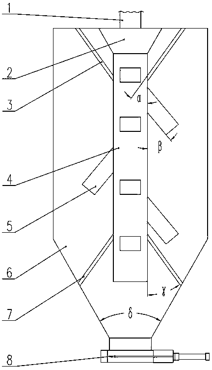
[0014] refer to figure 1 Among them, the present invention includes a silo and an anti-segregation device. The silo includes a feed chute (1), a feed hopper (2), a silo body (6) and a discharge valve (8), and the feed chute (1) is fixed on the upper cover of the silo body (6) , the outlet of the feed chute (1) is docked with the feed hopper (2); the bin body (6) mainly includes the upper cylinder and the lower cone, and in order to ensure smooth discharge, the cone The cone angle δ of the body is set to 60°~65°; the discharge valve (8) is installed on the discharge pipe at the lower end of the bin body (6).

[0015] The anti-segregation device includes a main pipe (4) and multiple side pipes (5); the main pipe (4) is a square pipe with a quadrilateral cross-section, and is fixed on the bin body (6) by the upper bracket (3) and the lower bracket (7). inside, and make the upper end of the main pipe connect with the feed hopper (2), and the lower end is suspended in the air, so...


PUM


Abstract

The invention discloses an anti-separation dry sand silo and method. The anti-separation dry sand silo comprises a stock silo and an anti-separation device. The anti-separation dry sand silo is characterized in that the stock silo comprises a feed articulated chute, a feed hopper, a silo body and a discharge valve, the feed articulated chute is fixed on the upper cover plate of the silo body, the silo body mainly comprises an upper cylinder body and a lower cone cylinder body, and the discharge valve is mounted on a discharge pipe at the lower end of the silo body. The anti-separation device comprises a main pipe and a plurality of side pipes, the main pipe is fixed inside the silo body through an upper support and a lower support, the upper end of the main pipe is made to be in butt joint with the feed hopper, and the lower end of the main pipe is hung in the air. The anti-separation dry sand silo and method have the advantages that separation is effectively prevented from being generated on dry sand in the process that the dry sand flows into the silo, the integrated falling down of sand materials in the discharge process of the dry sand silo is achieved, the falling down process is clean and smooth, production cost is saved, and quality of finished mortar products is guaranteed. The anti-separation dry sand silo is simple in structure, good in anti-separation effect, high in operational reliability, and capable of effectively improving quality of finished mortar products, and has wide practicability.

Description

technical field [0001] The invention relates to a dry sand bin, which belongs to the technical field of preventing segregation of the dry sand bin of a dry-mixing mortar station, in particular to a dry sand bin and a method for preventing segregation. Background technique [0002] At present, the storage warehouse for storing dry sand in the dry-mixed mortar station mainly adopts a vertical drop structure, so that the dried dry sand directly falls into the warehouse. Due to the large internal drop of the warehouse and different particle sizes ( 0-5mm) dry sand has different specific gravity, and the speed of free fall is different. During storage and accumulation, dry sand naturally forms a cone shape, and dry sand with finer particle size naturally accumulates upward with the cone, while relatively When the dry sand material with coarser particle size slides down naturally from around the cone, it is very easy to produce secondary separation, which leads to the "segregation...

Claims


Application Information

Patent Timeline
Patent Type & Authority Applications(China)
IPC IPC(8): B65D88/64
Inventor 王忠利马玲刘英李宝平唐锋许豫平
Owner 徐州沃土资产管理有限公司
Why Eureka
Try Eureka