

Novel nozzle and fin combined type vortex reduction system
A composite, nozzle technology, used in non-variable-capacity pumps, cooling of turbines/propulsion devices, cooling of engines, etc., can solve the problems of viscous dissipation of airflow, unfavorable airflow, small flow area, etc., to reduce flow Obstruction, avoids widening and narrowing, and has the effect of large circulation area
- Summary
- Abstract
- Description
- Claims
- Application Information
AI Technical Summary
Problems solved by technology
Method used
Image

Examples
Embodiment Construction
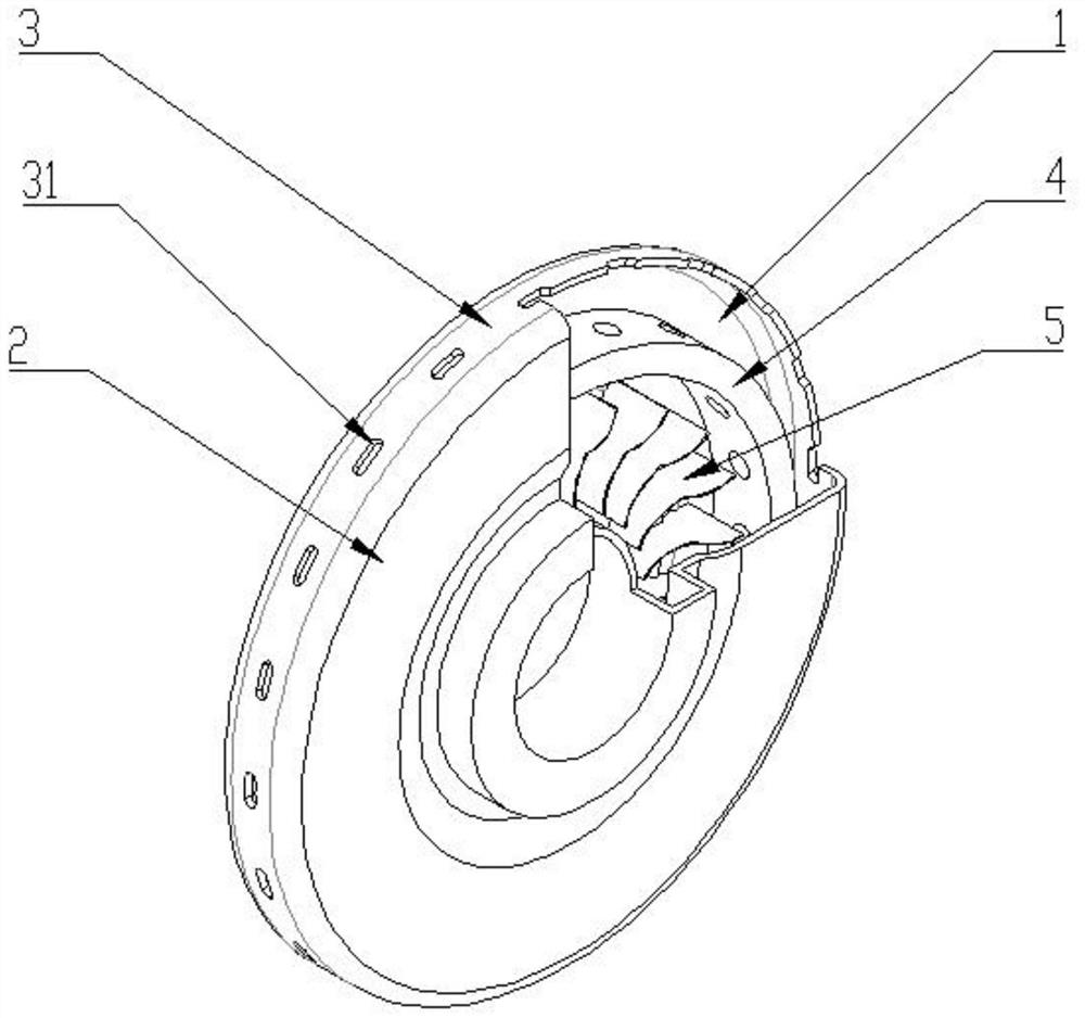
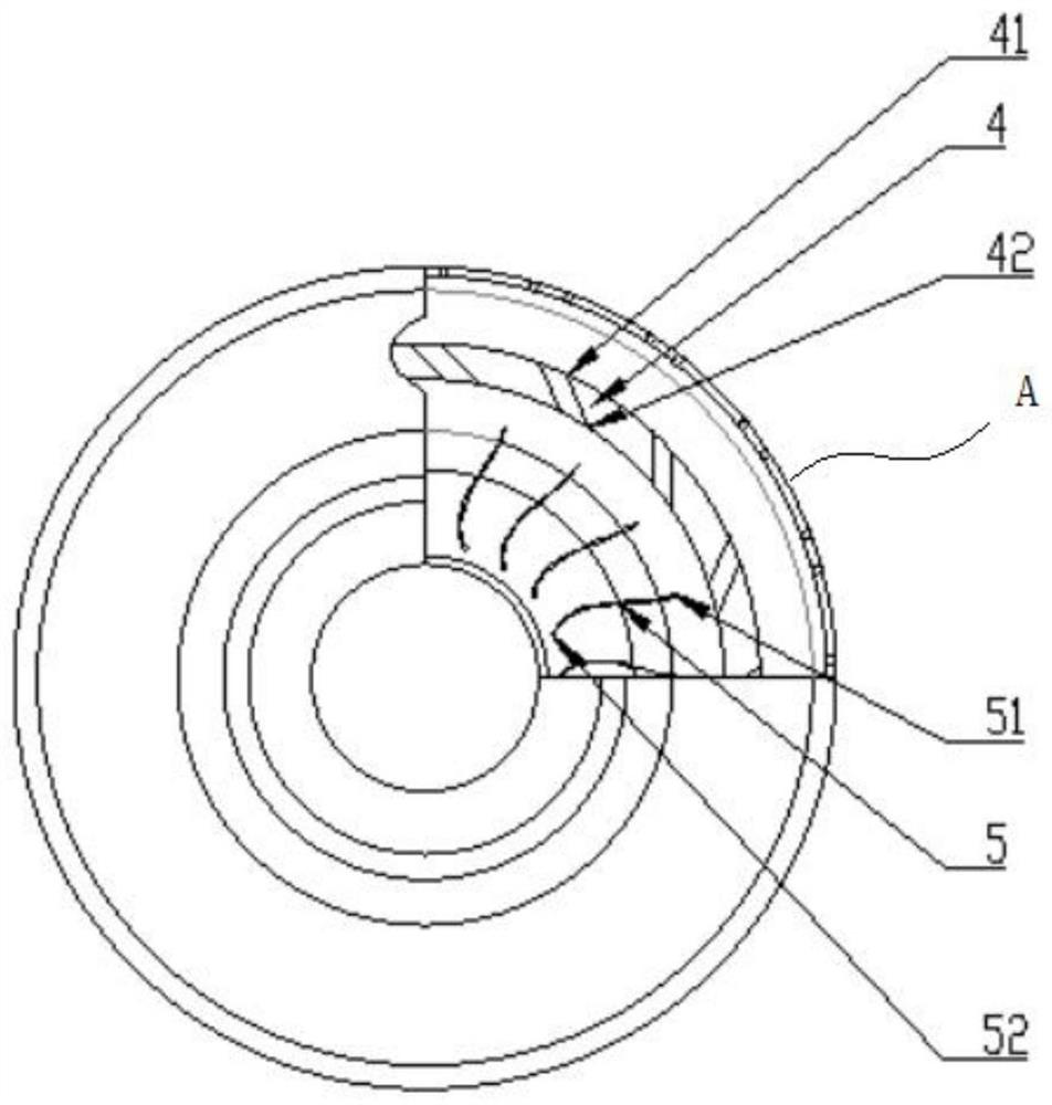
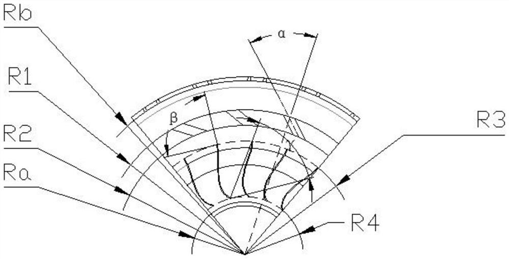
[0032] figure 1 It is a schematic perspective view of a novel nozzle-fin composite vortex reduction system according to an embodiment of the present application. figure 2 yes figure 1 Schematic front view of the nozzle-fin composite vortex reduction system shown. image 3 yes figure 1 A schematic top view of the nozzle-fin composite vortex reduction system shown.
[0033] Such as figure 1 shown, see also Figure 2-Figure 3 , this embodiment provides a novel nozzle-fin composite vortex reduction system, which is arranged at the radial flow section of the compressor of the secondary air system of the aeroengine. The compressor includes: a front-stage compressor disk 1 and a rear-stage compressor disk 2 arranged correspondingly on both sides, a drum 3 extending vertically along the outer edges of the compressor disks on both sides, and the compressor disks on both sides The disc and the drum 3 form an inner disc cavity. The drum 3 is provided with several drum holes 31 . ...
PUM
 Abstract
Description
Claims
Application Information