Image forming apparatus

a color image and forming apparatus technology, applied in the field of electrographic color image forming apparatuses, can solve the problems of difficult to ensure the coupling time of the developing device with the coupling in the difficulty of reducing the size of the main apparatus body, and the cost reduction, so as to achieve the effect of reducing the cost, reducing the size of the main apparatus body, and reducing the cos

Active Publication Date: 2010-03-04
CANON KK
View PDF6 Cites 65 Cited by
  • Summary
  • Abstract
  • Description
  • Claims
  • Application Information

AI Technical Summary

Benefits of technology

[0019]The present invention provides a rotary-type image forming apparatus that allows for good image quality as well as a smaller main apparatus body and lower costs.

Problems solved by technology

However, the rotary-type image forming apparatus of the related art has the following problems.
Therefore, it is difficult to achieve size reduction of the main apparatus body, as well as cost reduction.
However, if the operation for moving the toner bearing member into and out of contact with the image bearing member is to be performed by utilizing the rotation of the developing-device support member, it becomes difficult to ensure the time for engaging the coupling in the developing device with the coupling in the main apparatus body.
If the toner bearing member in a non-rotating state comes into contact with the surface of the image bearing member, the toner on the toner bearing member becomes scraped off by the image bearing member, creating a fog on the surface of the image bearing member and thus leading to an image defect.

Method used


Image

  • Image forming apparatus
  • Image forming apparatus
  • Image forming apparatus

Examples


first embodiment

[0033]An image forming apparatus according to a first embodiment of the present invention will now be described with reference to FIGS. 1 to 9.

[0034]Schematic Configuration of Image Forming Apparatus

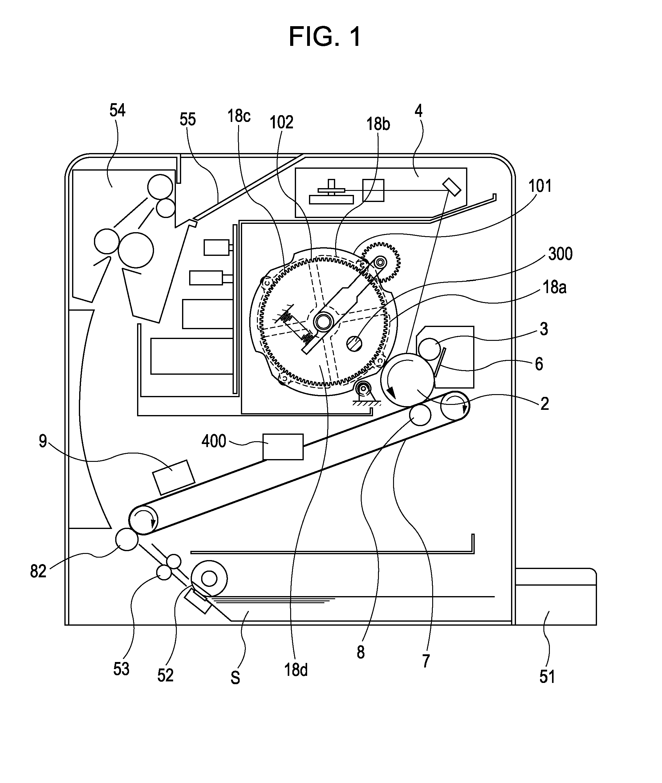
[0035]FIG. 1 schematically illustrates the image forming apparatus according to the first embodiment. In the first embodiment, a rotary-type (electrophotographic) color laser printer is used as the image forming apparatus.

[0036]The color laser printer includes a rotatable photosensitive drum (image bearing member) 2. The photosensitive drum 2 is surrounded by a charge roller 3 for uniformly charging the surface of the photosensitive drum 2, an exposure unit 4 for irradiating the surface of the photosensitive drum 2 with a laser beam to form an electrostatic latent image thereon, and a cleaning device 6 that cleans the surface of the photosensitive drum 2.

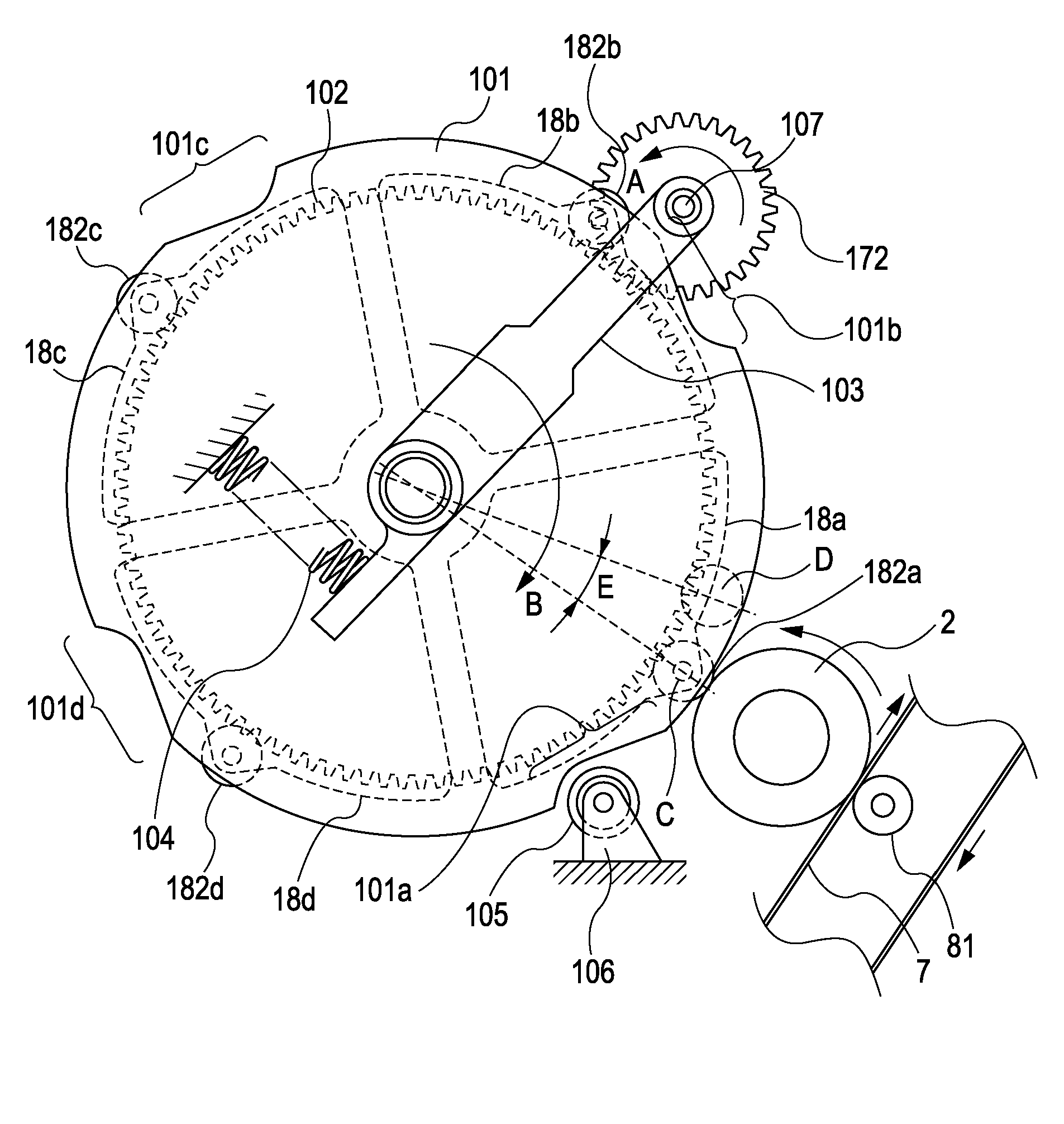
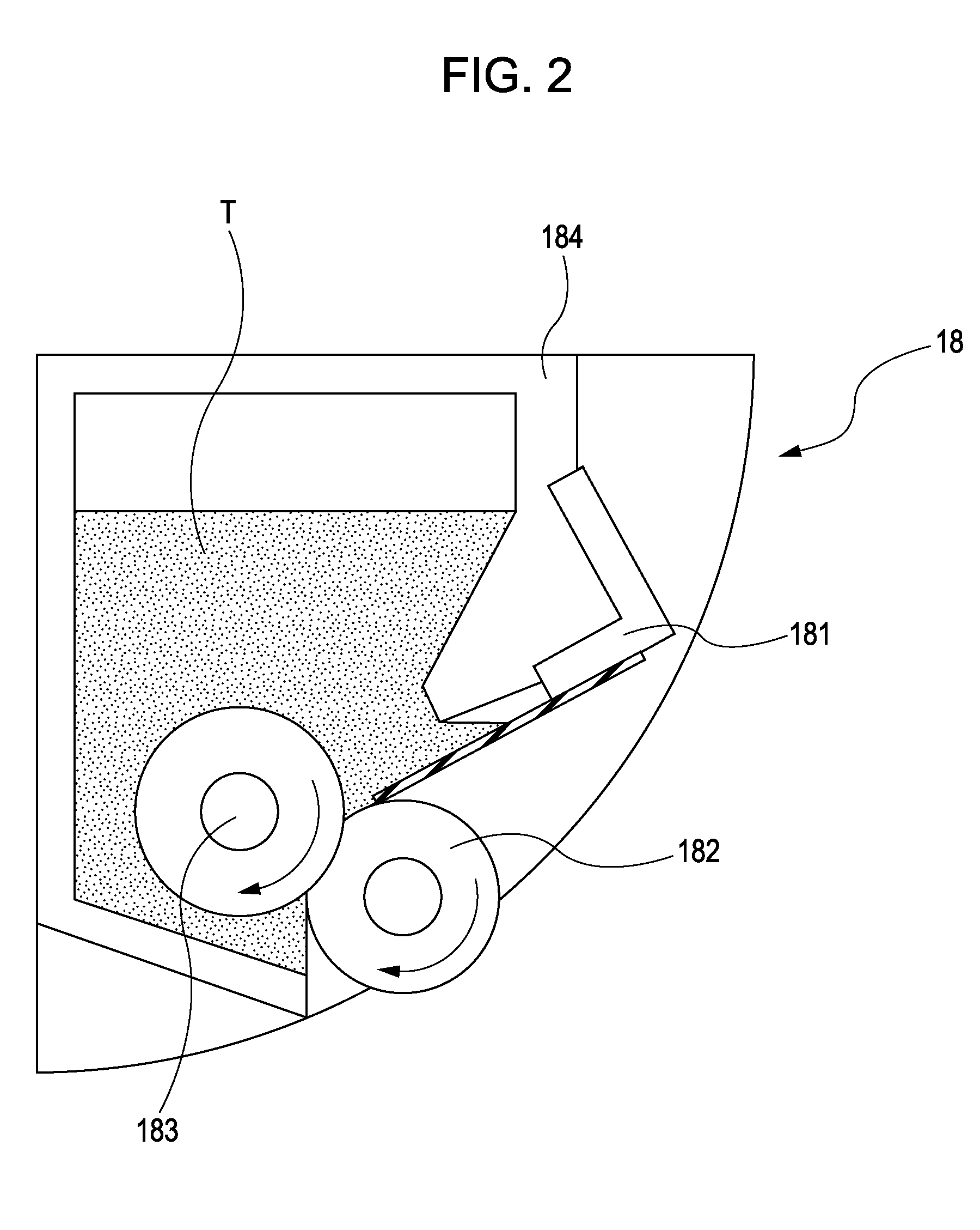
[0037]Developing devices 18a to 18d are respectively provided for the four colors of toners (i.e., yellow, magenta, cyan, and black). T...

second embodiment

[0139]An image forming apparatus according to a second embodiment of the present invention will now be described with reference to FIG. 10. Since the configuration of the image forming apparatus according to the second embodiment and the configuration of the developing devices are substantially the same as those of the image forming apparatus according to the first embodiment, the descriptions thereof will not be repeated. The following description will only be directed to the differences from the first embodiment.

[0140]The second embodiment has a characteristic feature in the control of the rotational driving of the rotary 102. In the first embodiment, the temporary stopping time period of the rotary 102 before the developing device 18 reaches the development position is a time period in which the pins 302a and 302b and the claws 201a and 201b can properly engage with each other.

[0141]In contrast, in the second embodiment, the rotational driving of the rotary 102 is controlled such...

third embodiment

[0146]An image forming apparatus according to a third embodiment of the present invention will now be described with reference to FIG. 11. Since the configuration of the image forming apparatus according to the third embodiment and the configuration of the developing devices are substantially the same as those of the image forming apparatus according to the first embodiment, the descriptions thereof will not be repeated. The following description will only be directed to the differences from the first embodiment.

[0147]The third embodiment has a characteristic feature in the control of the rotational driving of the rotary 102. In the first embodiment, the temporary stopping time period of the rotary 102 before the developing device 18 reaches the development position is a time period in which the pins 302a and 302b and the claws 201a and 201b can properly engage with each other (see STEP 2 in FIG. 9).

[0148]In contrast, in the third embodiment, instead of completely stopping the rotar...


PUM


Abstract

In a rotary-type image forming apparatus, rotation of a rotary is temporarily stopped at a position where a coupling member and a drive transmission member are engageable with each other, and a developing roller is set in a rotating state. Subsequently, the rotary is rotated so as to bring the developing roller into contact with a surface of a photosensitive drum.

Description

BACKGROUND OF THE INVENTION[0001]1. Field of the Invention[0002]The present invention relates to electrophotographic color image forming apparatuses that employ a rotary-method development process.[0003]2. Description of the Related Art[0004]In a full-color image forming apparatus of the related art that includes a single image bearing member and a rotatable support member integrally supporting a plurality of developing devices, the image forming apparatus employs a development process in which the developing devices are sequentially switched at a predetermined timing so as to develop an electrostatic latent image formed on the surface of the image bearing member.[0005]An image forming apparatus that develops an electrostatic latent image formed on the surface of a single image bearing member by using a rotatable developing-device support member (i.e., a rotary) that integrally supports a plurality of developing devices in this manner to sequentially switch the developing devices is...

Claims


Application Information

Patent Timeline
Patent Type & Authority Applications(United States)
IPC IPC(8): G03G15/08
CPCG03G15/0818G03G2215/0154G03G15/0173G03G2215/0177G03G15/0121G03G2215/0164G03G15/00G03G15/06
Inventor ADACHI, MOTOKIKAWAGUCHI, YUJIKAWASAKI, SHUHEIAOKI, DAISUKE
Owner CANON KK
Why Eureka
Try Eureka