Cutting tool with cutting insert having multiple cutting edges, and cutting insert therefor

Inactive Publication Date: 2010-03-11
SECO TOOLS AB
View PDF13 Cites 14 Cited by
  • Summary
  • Abstract
  • Description
  • Claims
  • Application Information

AI Technical Summary

Problems solved by technology

When the cutting edges become dull, it is necessary to remove them from the toolholder, sharpen them or replace them, and then rebraze them onto the toolholder.

Method used


Image

  • Cutting tool with cutting insert having multiple cutting edges, and cutting insert therefor
  • Cutting tool with cutting insert having multiple cutting edges, and cutting insert therefor
  • Cutting tool with cutting insert having multiple cutting edges, and cutting insert therefor

Examples


Embodiment Construction

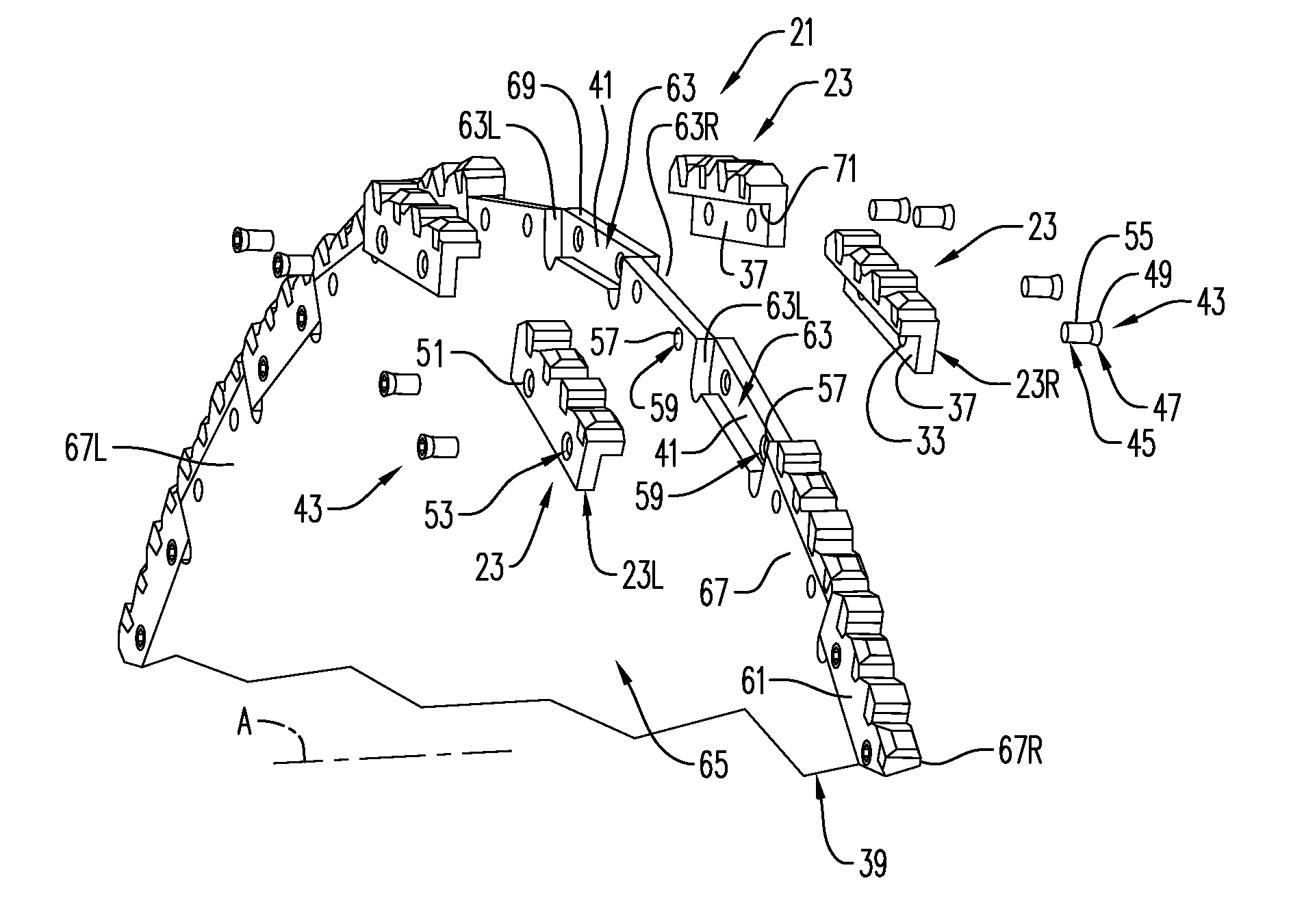
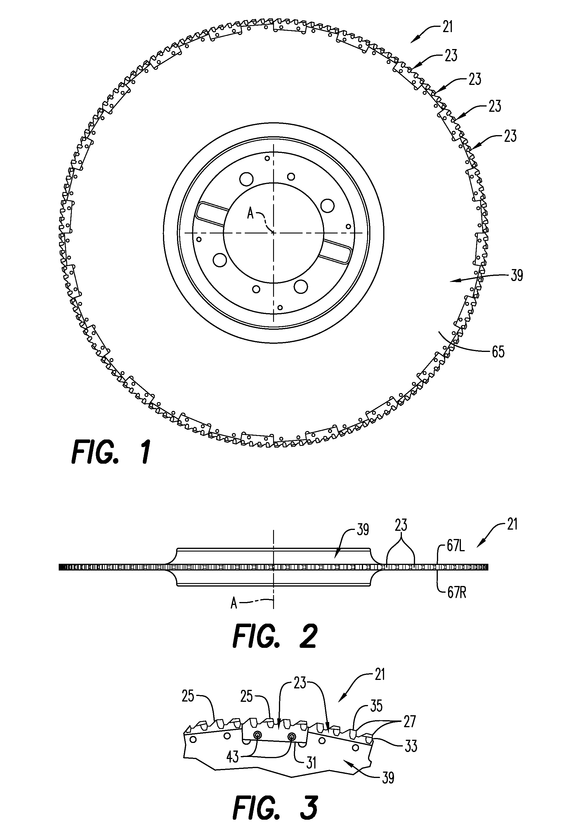
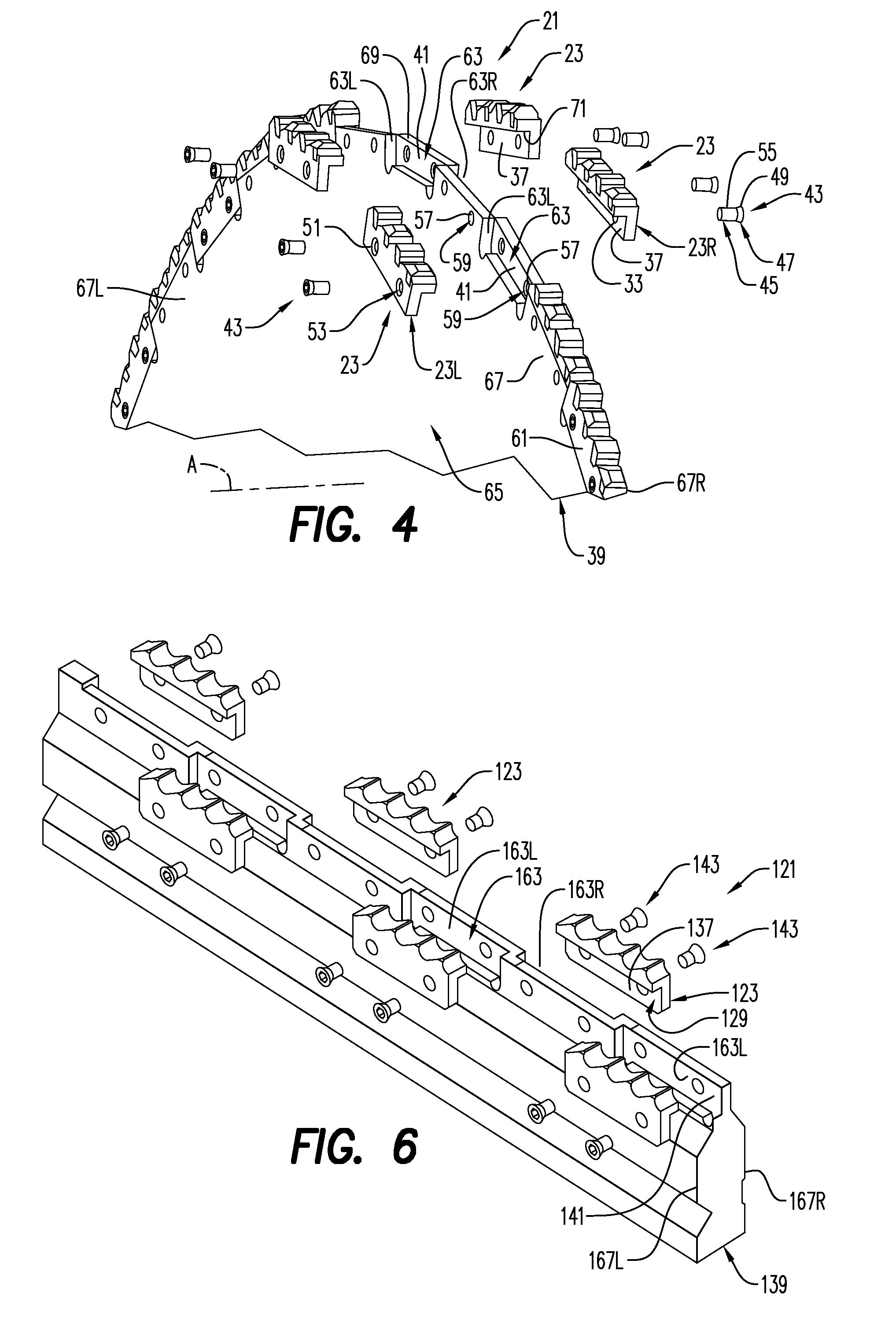
[0024]A cutting tool 21 according to an aspect or the present invention is seen in FIGS. 1-4. The cutting tool 21 includes a cutting insert 23 and ordinarily, a plurality of cutting inserts. At least some of the cutting inserts 23 are ordinarily, but not necessarily, identical to one another.

[0025]As seen with reference to the exemplary insert 23 shown in FIGS. 17A-17F, the inserts 23 each comprise a top side 25 comprising a plurality of cutting edges 27. The cutting edges 27 are arranged one after another in a longitudinally axial direction of the insert 23 and extend substantially perpendicularly to a longitudinal, vertical axial plane L (FIGS. 17B, 17C, 17E) of the insert. A side wall 29 extends substantially perpendicularly relative to a plane P of the top side 25 of the insert. The plane P of the top side 25 is ordinarily an imaginary plane that can be taken at some arbitrary point relative to the top side, such as extending through an uppermost one of the cutting edges and par...


PUM

PropertyMeasurementUnit
anglesaaaaaaaaaa
distancesaaaaaaaaaa
radiusaaaaaaaaaa

Abstract

A cutting tool includes a cutting insert. The insert includes a top side including a plurality of cutting edges, the cutting edges being arranged one after another in a longitudinally direction of the insert and extending substantially perpendicularly to a longitudinal, vertical axial plane of the insert. The insert includes a side wall extending downwardly relative to a plane of the top side of the insert, the side wall including a side supporting surface. The cutting tool includes a toolholder. The toolholder includes a side abutment surface against which the side supporting surface of the insert is adapted to be supported. A clamp is provided for clamping the side supporting surface of the insert against the side abutment surface of the toolholder.

Description

BACKGROUND AND SUMMARY[0001]The present invention relates to cutting tools with multiple cutting edges thereon and, more particularly, to cutting tools with cutting inserts having multiple cutting edges thereon.[0002]Rotating tools such as pipe cutters and reciprocating tools such as broaches typically have a large number of cutting edges thereon, arranged one after the other in a direction of cutting. Typically, inserts having a single or plural cutting edges are brazed onto a toolholder. When the cutting edges become dull, it is necessary to remove them from the toolholder, sharpen them or replace them, and then rebraze them onto the toolholder. It is desirable to provide a means for replacing or repairing cutting inserts on a cutting tool. having a large number of cutting edges thereon.[0003]According to an aspect of the present invention, an L-shaped cutting insert comprises a top side on a first leg of the insert, the top side comprising a plurality of cutting edges, the cuttin...

Claims


Application Information

Patent Timeline
Patent Type & Authority Applications(United States)
IPC IPC(8): B27B33/12
CPCB23D43/04B23D61/023B23D43/06Y10T83/9331Y10T83/9353
Inventor SCANDROGLIO, EMILIOBERNARDINELLI, PIETROKOSKINEN, JORMAHESSLERYD, LARS-MARTIN
Owner SECO TOOLS AB
Why Eureka
Try Eureka