
Air conditioner

a technology for air conditioners and airbags, applied in the field of air conditioners, can solve the problems of inaccurate calculation of floor and wall positions, and inability to accurately calculate floor and wall positions

Active Publication Date: 2010-03-11
MITSUBISHI ELECTRIC CORP
View PDF10 Cites 56 Cited by
  • Summary
  • Abstract
  • Description
  • Claims
  • Application Information

AI Technical Summary

Benefits of technology

[0012]The present invention attempts to solve the problem such as this, by providing an air conditioner having the spatial recognition and detection function for determining the room shape by integrally determining the temperature difference (temperature unevenness) information between the floor and the walls occurring during the air conditioning operation, a human body detection position log, and a capacity zone of the air conditioner.

Problems solved by technology

However, in a conventional room information detecting apparatus, when the wall and floor boundary cannot be favorably calculated by the two-dimensional infrared ray thermal image data, the positions of floor and walls cannot be calculated accurately either, so that it is difficult, in terms of a pattern recognition processing, to calculate the positions of floor and walls for an unknown room based on the calculated line image data.
However, the patent document 1 mentioned above does not disclose a space recognition technology for determining a room shape by integrally determining, based on an adaptive room condition in determining a floor, depending on a capacity zone, a temperature difference (temperature unevenness) between the floor and the walls occurring during the air conditioning operation, and a result of human body log.

Method used


Image

  • Air conditioner
  • Air conditioner
  • Air conditioner

Examples


first embodiment

[0067]At first, an outline of the present embodiment will be described. The air conditioner (the indoor unit) provides an infrared sensor that detects a temperature while scanning the temperature detection target area. The infrared sensor detects a presence of heat generating device or human by performing a heat source detection. The air conditioner performs an ideal control accordingly.

[0068]Generally, the indoor unit is installed on a wall, at a higher position of the room. There are various positions where the indoor unit can be installed with respect to right and left positions on the wall. The indoor unit may be substantially installed at a mid-position of the wall in the right and left direction, or in some cases it may be installed close to the right side wall or the left side wall, when viewed from the indoor unit. Hereinafter, the right and left direction of the room is defined as the right and left direction viewed from the indoor unit (the infrared sensor 3).

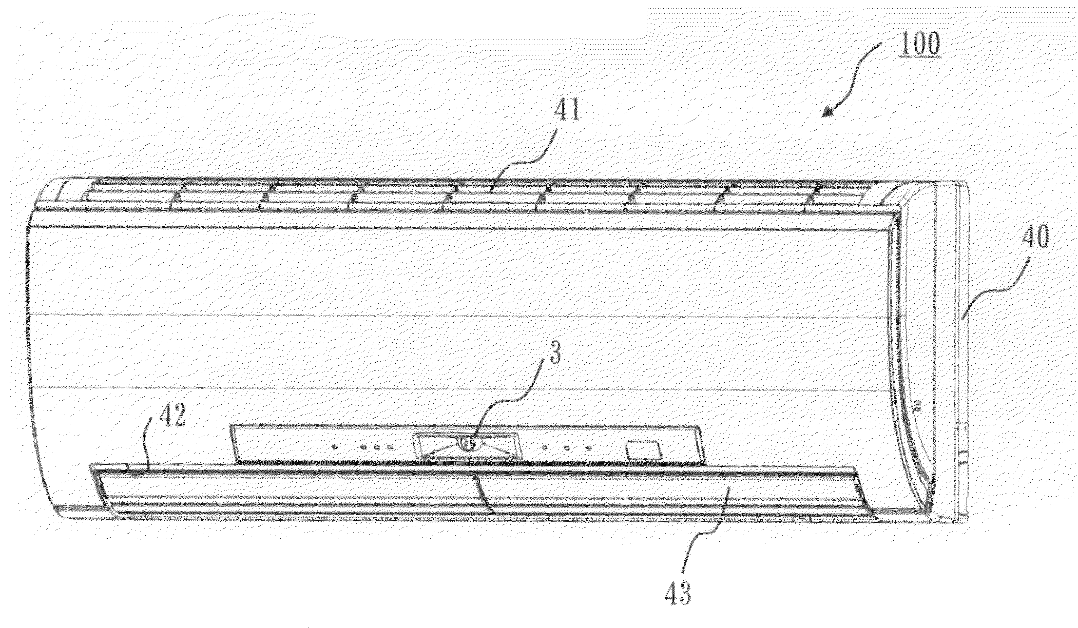
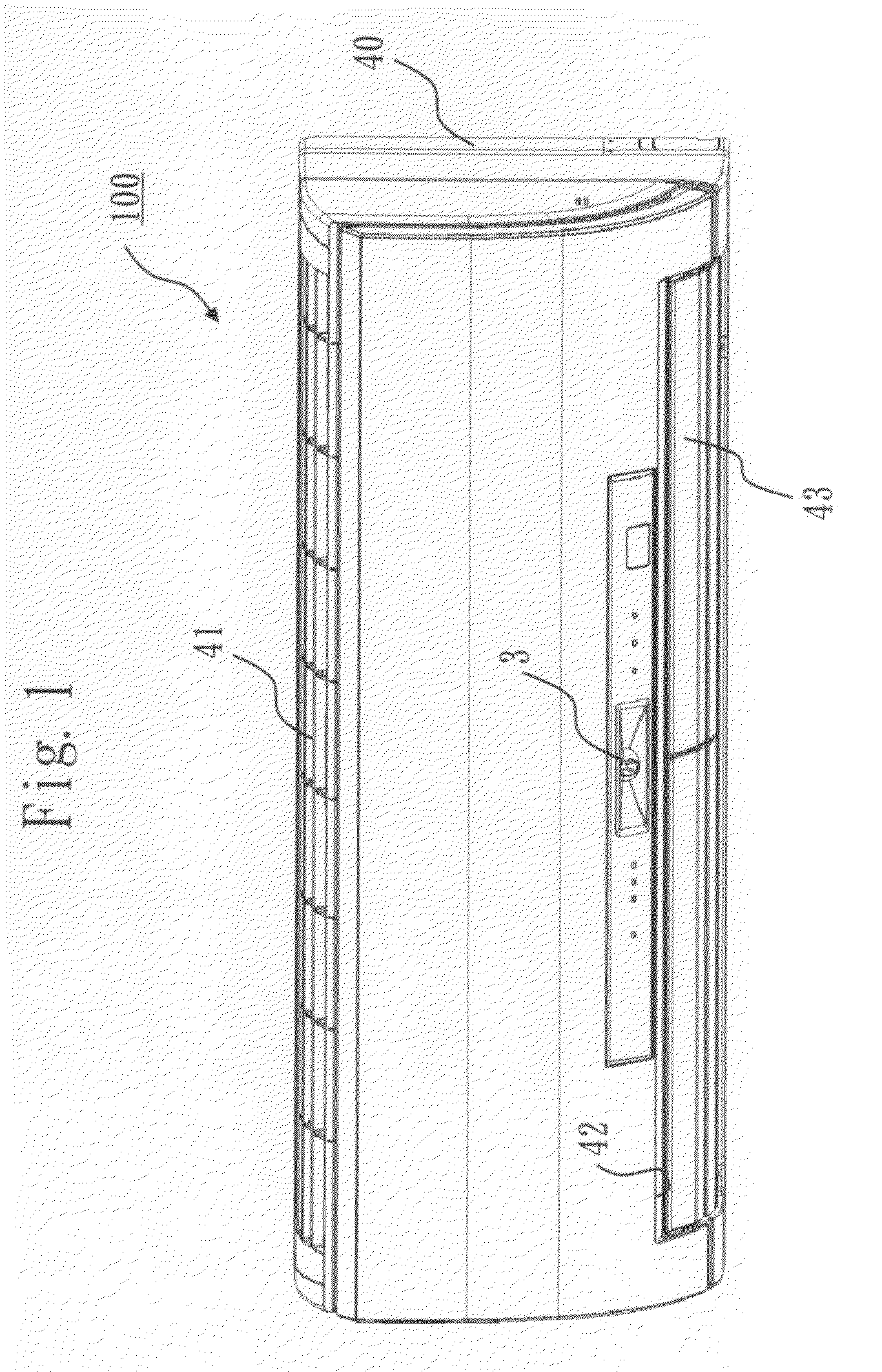
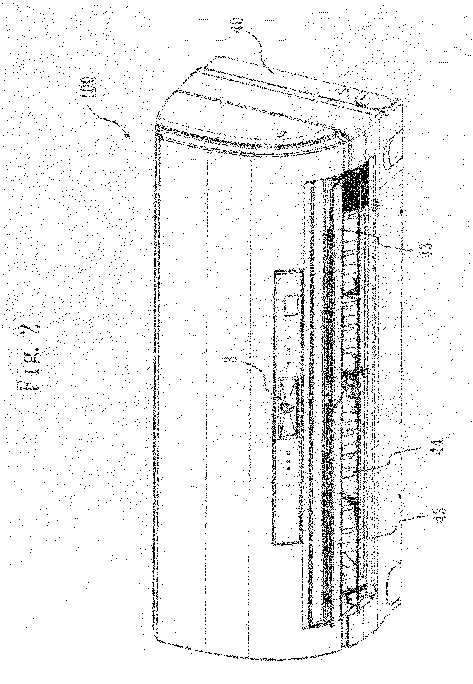
[0069]FIGS. 1...


PUM


Abstract

Disclosed is an air conditioner provided with a spatial recognition and detection function for deciding the room shape by integrally determining based on a temperature difference (the temperature unevenness) information between the floor and the walls occurring during the air conditioning operation, a human body detection position log, and a capacity zone of the air conditioner. The air conditioner of the present invention provides an infrared sensor and a control unit that controls the air conditioner by detecting a presence of heat generating device and human with the infrared sensor, wherein the control unit acquires a thermal image data of the room by scanning with the infrared sensor, and integrates three information indicated below to calculate a floor dimension inside the air conditioning area, and calculates the wall position within the air conditioning area on the thermal image data.(1) a room shape having the initial setting value and the shape limitation value calculated based on the capacity zone of the air conditioner and the remote controller installation position button setting;(2) a room shape calculated based on the temperature unevenness of the floor and wall occurring during the operation of the air conditioner; and(3) a room shape calculated based on the human body detection position log.

Description

BACKGROUND OF THE INVENTION[0001]1. Field of the Invention[0002]The present invention relates to an air conditioner.[0003]2. Description of the Related Art[0004]The air conditioner can increase an amenity on human present inside a room by utilizing information such as a room capacity and floor and wall temperatures etc., for example, by controlling a temperature, a wind direction and an air volume. The air conditioner can automatically perform a pleasant air conditioning operation.[0005]In case of detecting the room capacity and the floor and wall temperatures by using a two-dimensional thermal image data detected by a pyroelectric type infrared sensor, as a conventional commonly-used method, there is a method of calculating them after detecting a wall and floor boundary in the room by an image processing or an image recognition of an image data read from an image inputting apparatus.[0006]For example, a thermal image data detected by the image inputting unit is stored on a thermal ...

Claims


Application Information

Patent Timeline
IPC IPC(8): G05B15/00F24F11/02
CPCF24F11/0034F24F11/0012F24F2120/10F24F11/30F24F2110/10F24F11/56F24F2120/00F24F11/63
Inventor MATSUMOTO, TAKASHIWATANABE, SHINTAROKAGE, HIROSHIKATAOKA, YOSHIKUNIHIROSAKI, HIROSHI
Owner MITSUBISHI ELECTRIC CORP
Learn More