Drive for adjusting parts of seating and reclining furniture

a technology for adjusting parts and driving parts, which is applied in the direction of movable seats, sofas, gearing, etc., can solve the problems of increasing cost, increasing manufacturing costs, and increasing manufacturing costs, so as to improve adjustability, reduce manufacturing costs, and facilitate assembly

Inactive Publication Date: 2010-03-18
REMACRO MASCH & TECH (WUJIANG) CO LTD
View PDF7 Cites 16 Cited by
  • Summary
  • Abstract
  • Description
  • Claims
  • Application Information

AI Technical Summary

Benefits of technology

[0020]The drive of the present invention has a better adjustability within a limited inner space of the furniture. Moreover, the drive does not need to move, and the stroke length of the drive is independent from the cabinet size, so that the drive has a lower manufacturing cost and is easily assembled.

Problems solved by technology

Such a drive is particularly disadvantageous in that, its total length is determined by a necessary minimum length for guiding the lifting tube within the lifting tube receiving device plus a lifting path of the lifting tube.
Therefore, it is necessary to manufacture housings with different lengths of lifting tube receiving device within certain limits, and as a result, the manufacturing of the drives becomes considerably expensive.
Furthermore, such drive cannot be used in constricted spaces unobtrusively, for example, in adjustable seating and reclining furniture.
A large number of individual parts definitely require considerable efforts during assembling, and meanwhile result in an increased cost.

Method used


Image

  • Drive for adjusting parts of seating and reclining furniture
  • Drive for adjusting parts of seating and reclining furniture
  • Drive for adjusting parts of seating and reclining furniture

Examples


Embodiment Construction

[0032]The present invention is described in detail below with reference to the accompanying drawings.

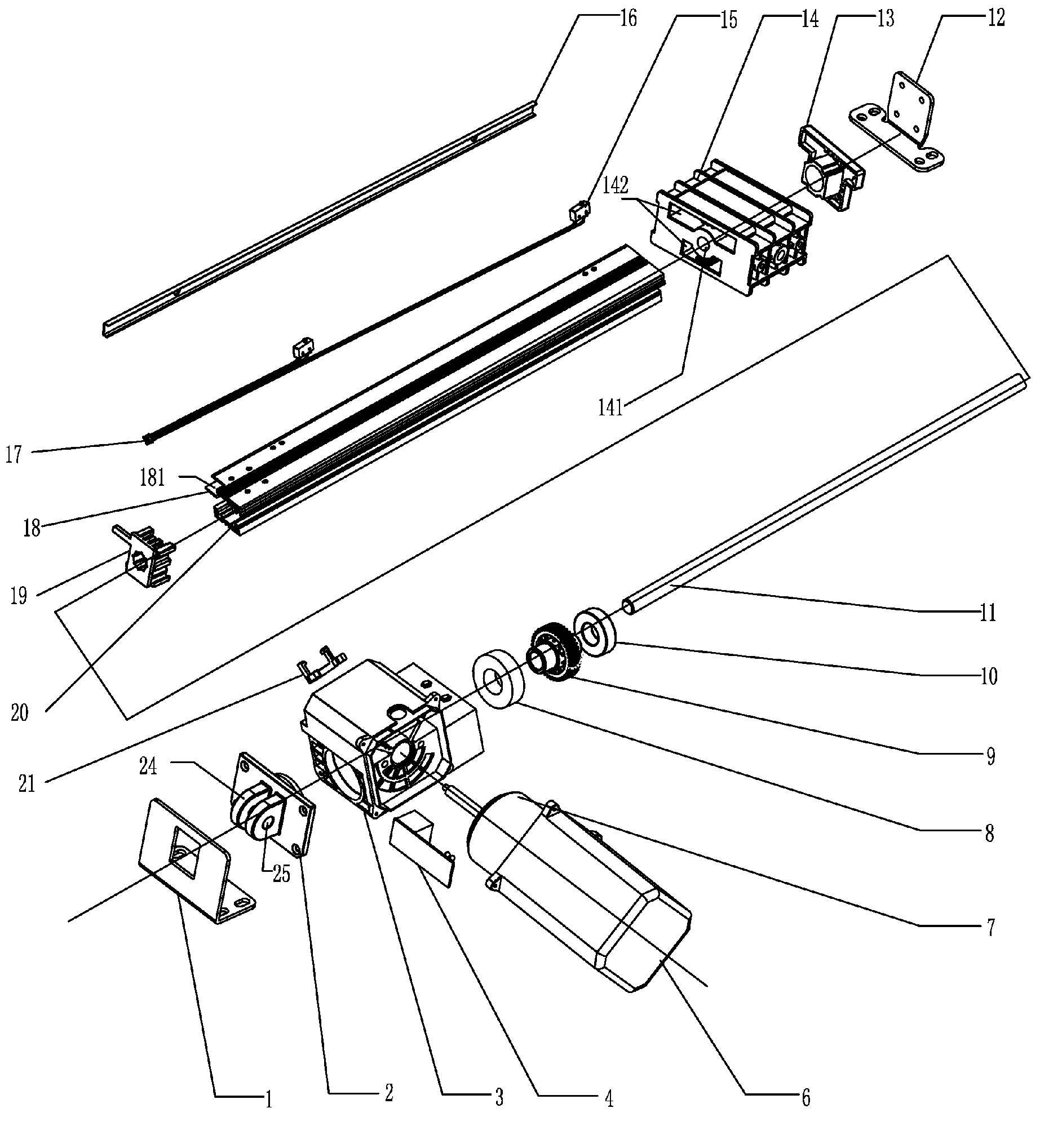
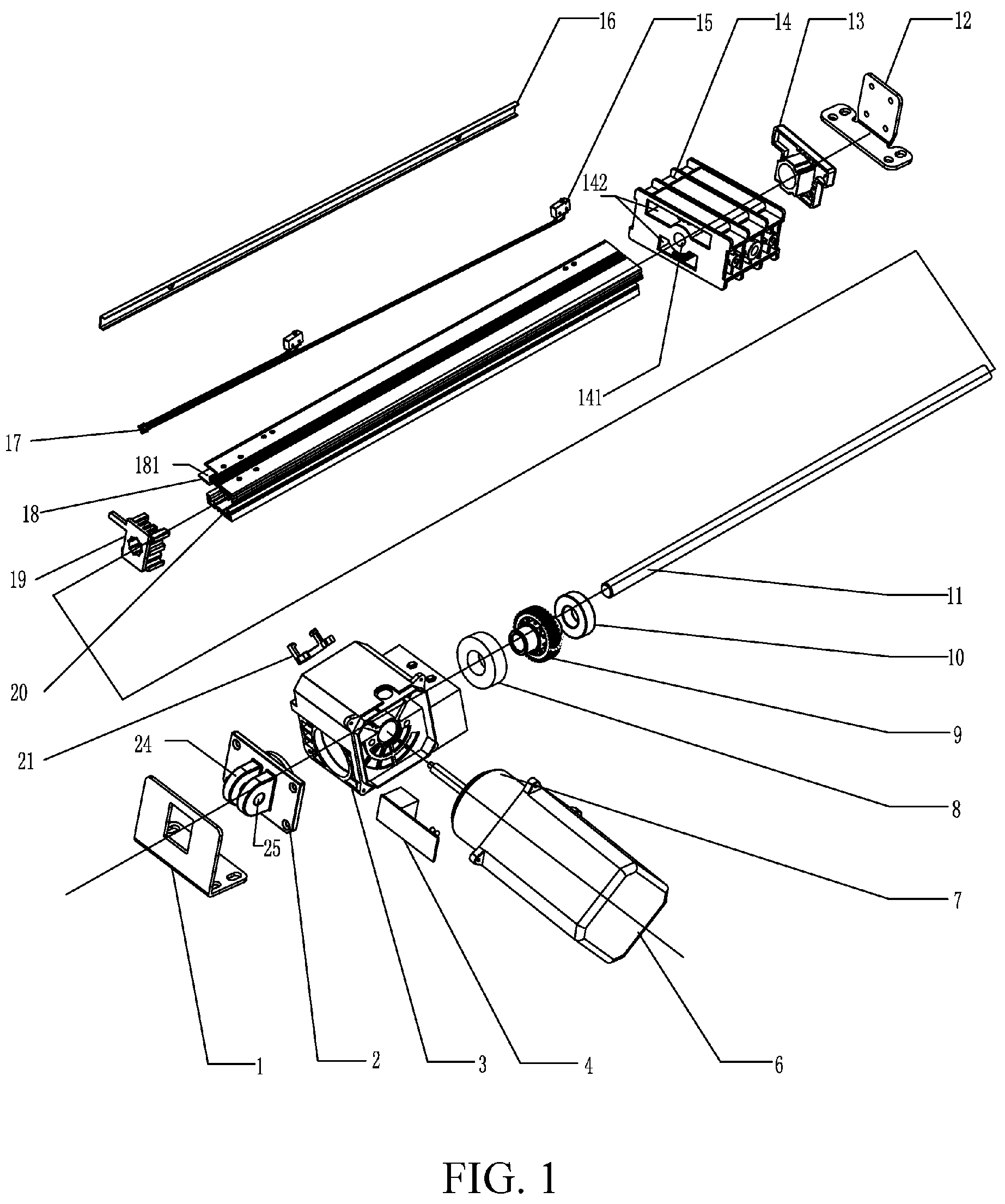
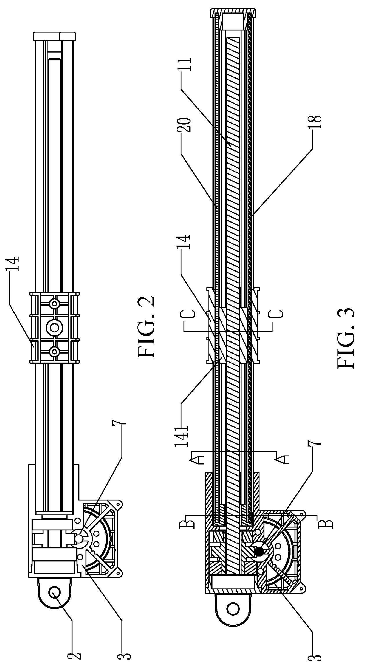
[0033]Referring to FIGS. 1 to 8, a drive for adjusting parts of seating and reclining furniture according to the present invention includes: an electric motor 7, disposed within a motor cover 6 of a cabinet 3 and engaged with a gear 9 connected to a lead screw 11 via one end of a drive shaft of the electric motor; and a slider 14, for moving rectilinearly back and forth in cooperation with the lead screw. The slider is provided with a drive nut 141 therein, which is screwed onto the lead screw to enable the slider to move rectilinearly. Two positioning grooves 142 are disposed on the slider in parallel with the nut. An upper guide rail 18 and a lower guide rail 20 are correspondingly disposed within each positioning groove. The upper guide rail is disposed with a groove 181 on one side surface thereof. The groove is provided for accommodating stroke switches 15 that are used for cont...


PUM


Abstract

A drive for adjusting parts of seating and reclining furniture is provided, which includes: an electric motor, disposed within a motor cover of a cabinet and engaged with a gear connected to a lead screw via one end of a drive shaft of the electric motor, and a slider, for moving rectilinearly back and forth in cooperation with the lead screw. The slider is provided with a drive nut therein, which is screwed onto the lead screw to enable the slider to move rectilinearly. One or more positioning grooves are disposed on the slider in parallel with the nut. Guide rails are correspondingly disposed in the positioning grooves. One end of each guide rail is fixed to the cabinet and the other end of each guide rail is fixed to a top stopper. Therefore, a better adjustability is achieved within a limited inner space of the furniture. Moreover, the drive does not need to move, and the stroke length of the drive is independent from the cabinet size thereof, so that the drive has a low manufacturing cost and is easily assembled.

Description

BACKGROUND OF THE INVENTION[0001]1. Field of the Invention[0002]The present invention relates to a drive for adjusting parts of seating and reclining furniture, and more particularly to a drive applicable to a chair and sofa.[0003]2. Related Art[0004]A drive of this kind is known from DE-GM 89 03 603, in which a mechanism, consisting of a gear connected to a spindle and a worm engaging the gear, is arranged inside a housing. The worm is driven by an electric motor fastened to a side surface of the housing. A nut, on which a lifting tube capable of moving in a lifting tube receiving device is fastened, is guided in a non-twisting manner on the spindle within the lifting tube receiving device protruding from the housing. The lifting tube can be easily adjusted if this drive is fixed in a pivoting manner via the receiving device on the housing and the lifting tube is coupled with an adjuster for slatted bases.[0005]Such a drive is particularly disadvantageous in that, its total length ...

Claims


Application Information

Patent Timeline
Patent Type & Authority Applications(United States)
IPC IPC(8): F16H29/20
CPCF16C29/02F16H25/20Y10T74/18576F16H2025/204Y10T74/18656F16H2025/2031A47C20/041
Inventor ZENG, WENLI
Owner REMACRO MASCH & TECH (WUJIANG) CO LTD
Why Eureka
Try Eureka