Mechanically compliant thermal spreader with an embedded cooling loop for containing and circulating electrically-conductive liquid

a technology of electrically conductive liquid and thermal spreader, which is applied in the direction of lighting and heating apparatus, instruments, and semiconductor/solid-state device details, etc., can solve the problem that the thermal spreader may not provide the desired level of performan

Active Publication Date: 2010-03-18
ROCKWELL COLLINS INC
View PDF104 Cites 56 Cited by
  • Summary
  • Abstract
  • Description
  • Claims
  • Application Information

AI Technical Summary

Problems solved by technology

Currently available thermal spreaders may not provide a desired level of performance.

Method used


Image

  • Mechanically compliant thermal spreader with an embedded cooling loop for containing and circulating electrically-conductive liquid
  • Mechanically compliant thermal spreader with an embedded cooling loop for containing and circulating electrically-conductive liquid
  • Mechanically compliant thermal spreader with an embedded cooling loop for containing and circulating electrically-conductive liquid

Examples


Embodiment Construction

[0049]Reference will now be made in detail to the presently preferred embodiments of the invention, examples of which are illustrated in the accompanying drawings.

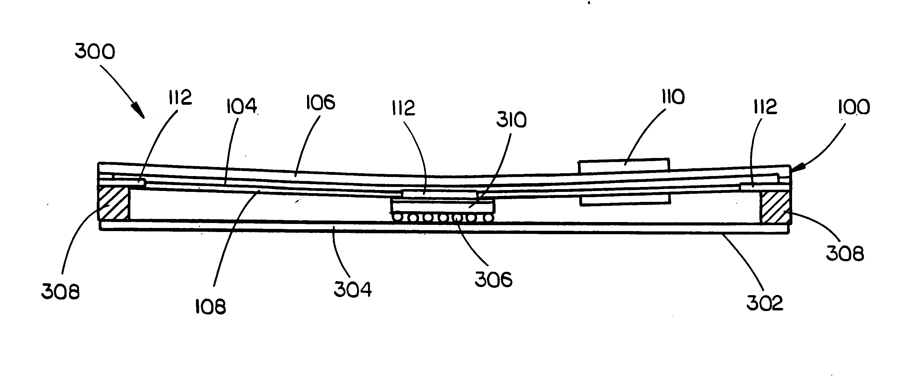
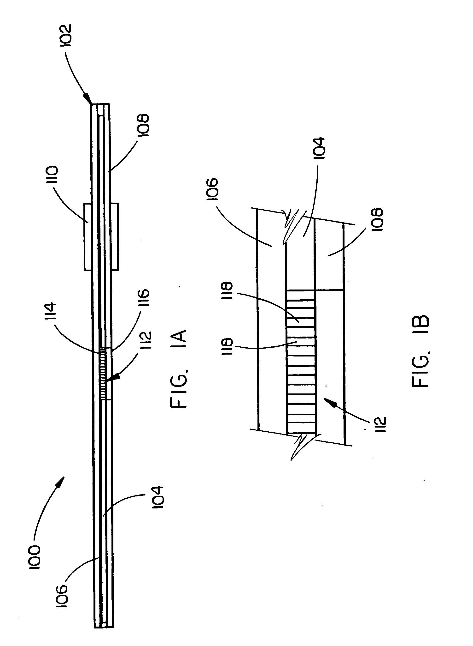
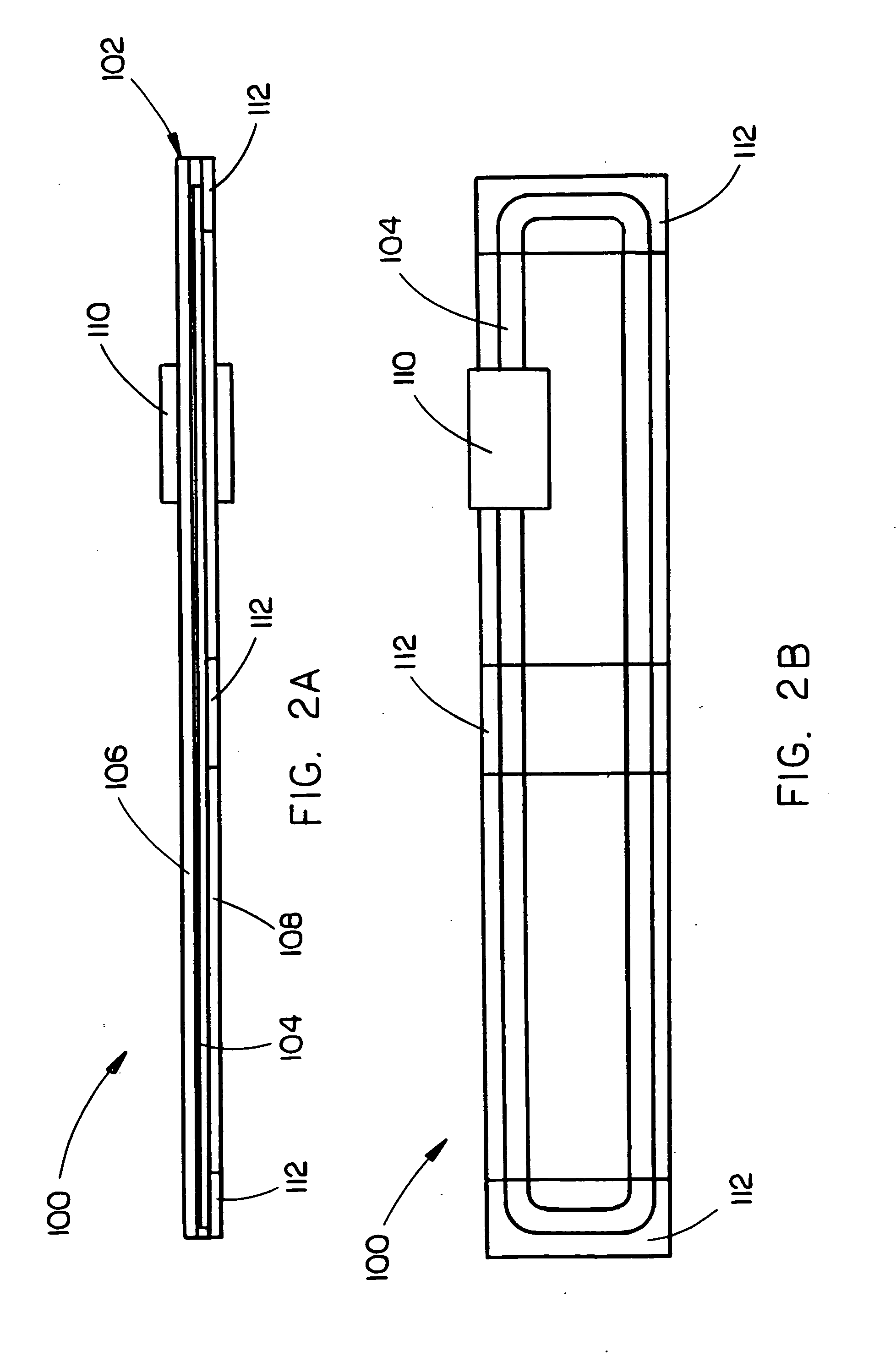
[0050]A thermal spreader / heat spreader may be used to diffuse and transport thermal energy from a heat source, such as an electronics component on a circuit board, to a lower temperature surface, such as a chassis in which the circuit board may be mounted. A heat spreader may be constructed of a material having a high thermal conductivity, such as metal (ex.—copper, aluminum), in order to reduce thermal gradients within the heat spreader so that the heat spreader may minimize the temperature of the heat source. When thermal gradients within a heat spreader are excessive, inserts (ex.—heat pipes, pyrolytic graphite inserts) having high effective thermal conductivities may be integrated with / into the heat spreader to offer / provide improved thermal paths.

[0051]Because of their structural properties, metal heat spreaders may b...


PUM

PropertyMeasurementUnit
thicknessaaaaaaaaaa
thicknessaaaaaaaaaa
melting temperatureaaaaaaaaaa

Abstract

The present invention is a thermal spreader for providing a high effective thermal conductivity between a heat source and a heat sink. The thermal spreader may include a mechanically flexible substrate. The mechanically flexible substrate may be at least partially constructed of organic materials. The mechanically flexible substrate may form an internal channel which is configured for containing an electrically-conductive liquid. The thermal spreader may further include a pump. The pump may be configured for being connected to the substrate and for circulating the electrically-conductive liquid within the internal channel. The thermal spreader may further include one or more thermally-conductive, rigid metal inserts. Each insert may be configured for being in thermal contact with the electrically-conductive liquid and the substrate and for promoting heat transfer between the thermal spreader and the electrically-conductive liquid.

Description

CROSS-REFERENCE TO RELATED APPLICATIONS[0001]The following patent applications are incorporated by reference in their entireties:Attorney Docket No.Express Mail No.Filing DateSer. No.08CR376KEEM 210498679 USSep. 12, 200808CR377KEEM 210498682 USSep. 12, 200808CR378KEEM 210498696 USSep. 12, 2008Further, U.S. patent application Ser. No. 12 / 116,126 entitled: System and Method for a Substrate with Internal Pumped Liquid Metal for Thermal Spreading and Cooling, filed May 6, 2008, (pending); U.S. patent application Ser. No. 11 / 508,782 entitled: Integrated Circuit Protection and Ruggedization Coatings and Methods filed Aug. 23, 2006, (pending); and U.S. patent application Ser. No. 11 / 732,982 entitled: A Method For Providing Near-Hermetically Coated Integrated Circuit Assemblies filed Apr. 5, 2006 (pending) are also hereby incorporated by reference in their entirety herein.FIELD OF THE INVENTION[0002]The present invention relates to the field of thermal management and particularly to a mecha...

Claims


Application Information

Patent Timeline
Patent Type & Authority Applications(United States)
IPC IPC(8): F28D15/00B21D53/02
CPCF28D15/00Y10T29/49353F28F21/065F28F21/089G06F1/20H01L23/473H01L2924/09701H01L2924/3011H05K7/20254F28F2250/08H01L2924/01019F28F2255/02H01L2224/16225H01L2224/73253F28F3/06B33Y80/00
Inventor WILCOXON, ROSS K.LOWER, NATHAN P.WOOLDRIDGE, JAMES R.DLOUHY, DAVID W.STRZELCZYK, ANTHONY J.
Owner ROCKWELL COLLINS INC
Why Eureka
Try Eureka