Cabinet for electronic device

Inactive Publication Date: 2010-03-18
FUNAI ELECTRIC CO LTD
View PDF23 Cites 17 Cited by
  • Summary
  • Abstract
  • Description
  • Claims
  • Application Information

AI Technical Summary

Benefits of technology

[0011]The present invention was conceived in light of the above-mentioned problems. One object of the present invention is to provide a cabinet

Problems solved by technology

When the number of screws is reduced and the protruding length of the engagement protrusions (hooks) is increased in the conventional cabinet, a problem is that the engagement protrusion is prone to breaking when the front cabine

Method used


Image

  • Cabinet for electronic device
  • Cabinet for electronic device
  • Cabinet for electronic device

Examples


Example

[0024]A preferred embodiment of the present invention will now be explained with reference to the drawings. It will be apparent to those skilled in the art from these disclosures that the following descriptions of the preferred embodiment of the present invention are provided for illustration only and not for the purpose of limiting the invention as defined by the appended claims and their equivalents.

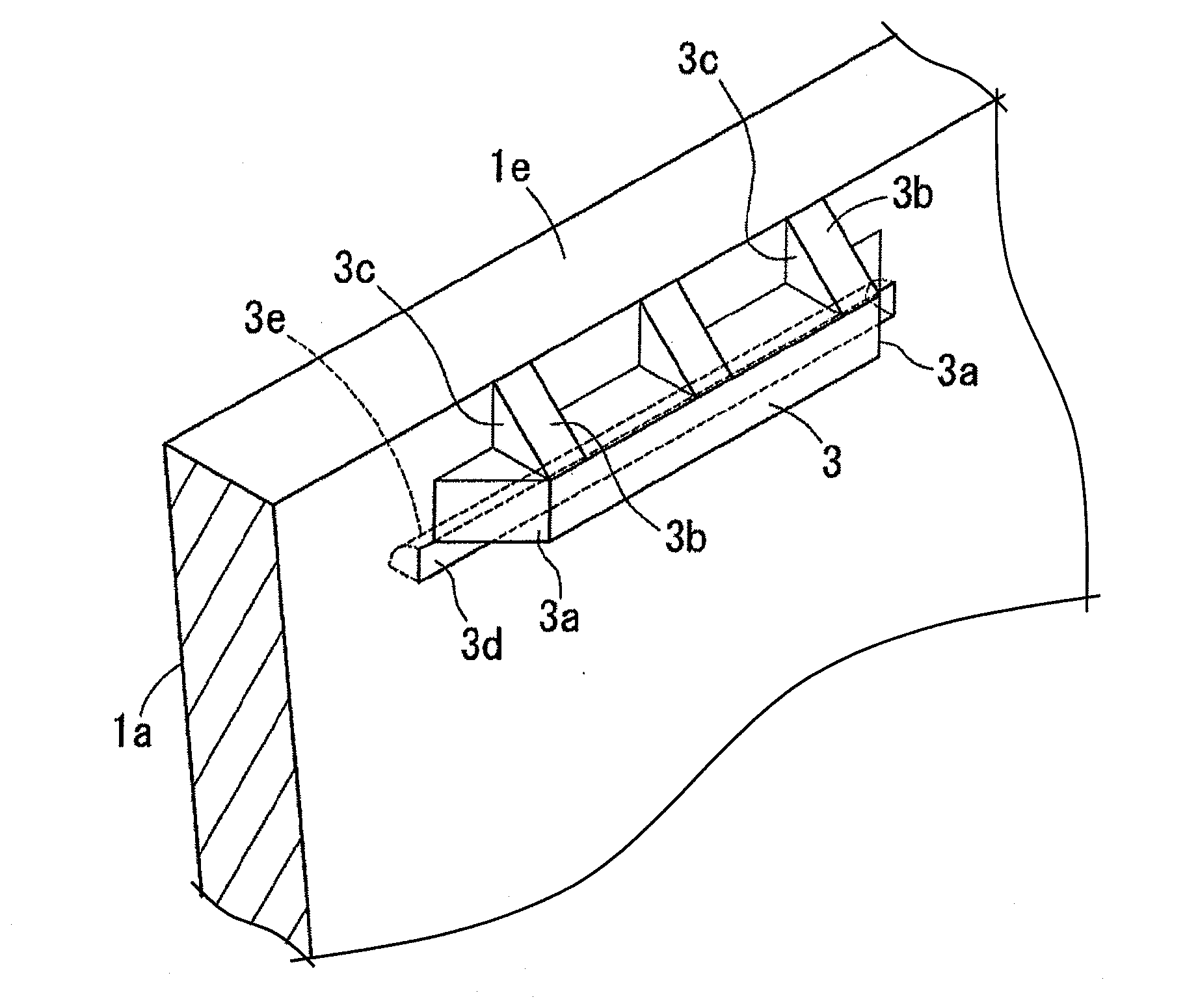
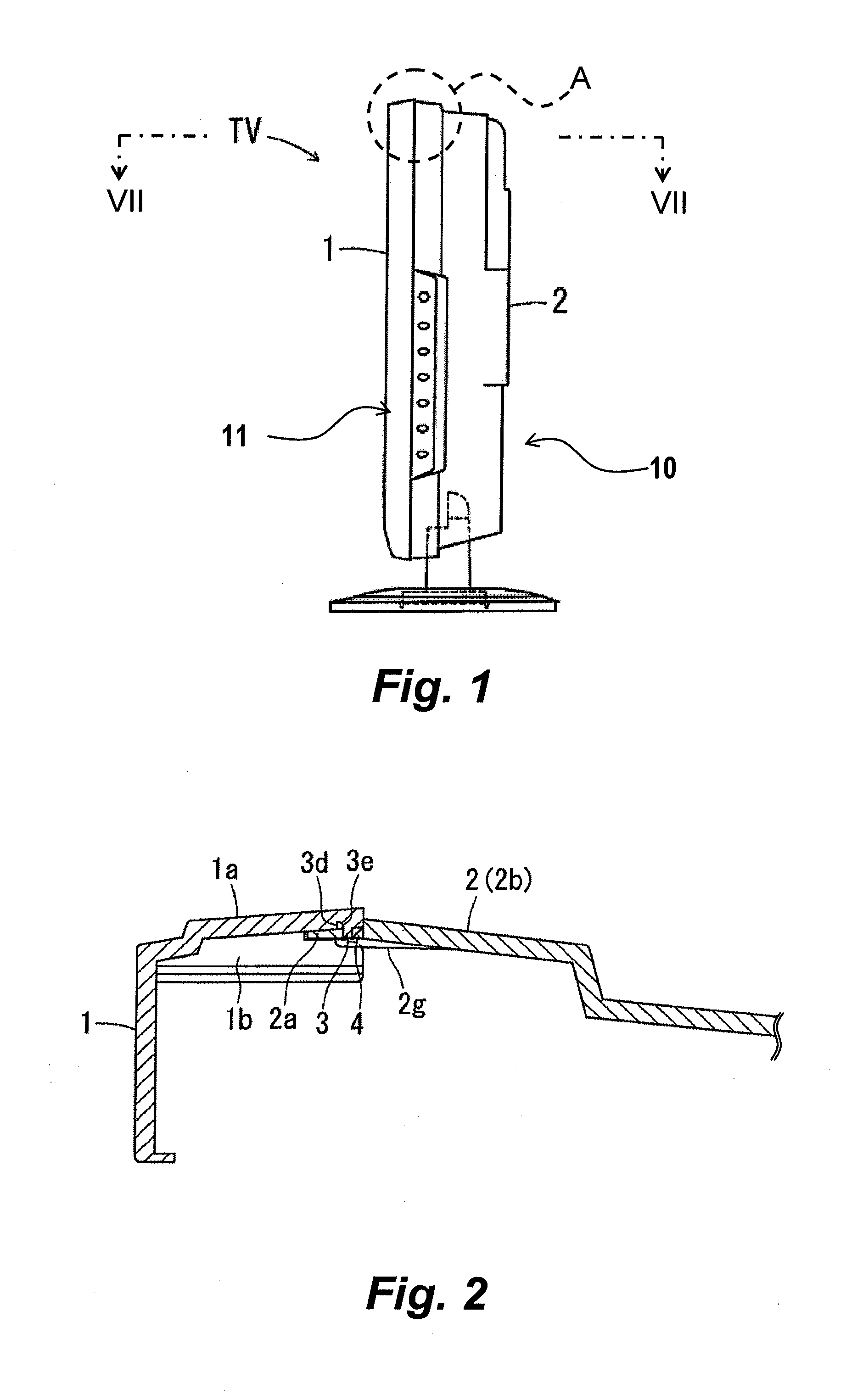
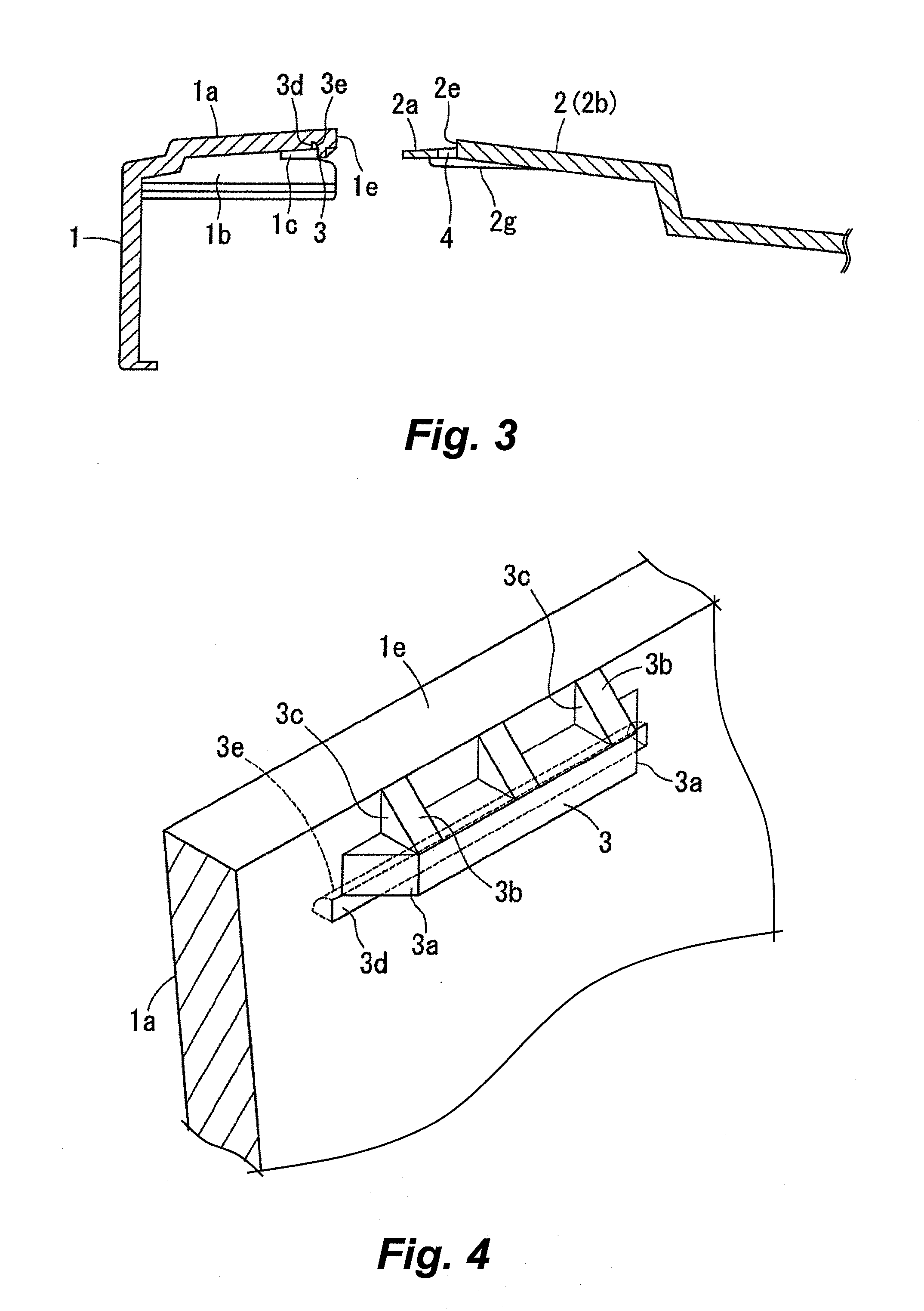
[0025]FIG. 1 is a side elevational view of a liquid crystal television TV. The liquid crystal television TV has a liquid crystal module (not shown), a cabinet 10 and a control key unit 11. The liquid crystal module includes a liquid crystal panel (not shown) to display image. The cabinet 10 has a front cabinet (e.g., second cabinet member) 1 and a rear cabinet (e.g., first cabinet member) 2, and houses the liquid crystal module within an inside space (inner side) of the cabinet 10 defined by the front cabinet 1 and the rear cabinet 2. The front cabinet 1 is rectangular when viewed from...


PUM


Abstract

A cabinet for an electronic device includes a first cabinet member and a second cabinet member. The first cabinet member has a first wall section with an engagement hole. The second cabinet member is fixedly coupled to the first cabinet member. The second cabinet member has a second wall section, an engagement protrusion and a recess. The engagement protrusion is formed on the second wall section and is engaged with the engagement hole of the first wall section. The recess is formed on the second wall section along a base portion of the engagement protrusion. The recess has a rounded portion extending between the base portion of the engagement protrusion and a bottom portion of the recess.

Description

CROSS-REFERENCE TO RELATED APPLICATIONS[0001]This application claims priority to Japanese Patent Application No. 2008-234550, filed on Sep. 12, 2008. The entire disclosure of Japanese Patent Application No. 2008-234550 is hereby incorporated herein by reference.BACKGROUND OF THE INVENTION[0002]1. Field of the Invention[0003]The present invention generally relates to a cabinet. More specifically, the present invention relates to a cabinet for an electronic device.[0004]2. Background Information[0005]A conventional cabinet of an electronic device, such as a liquid crystal television set, includes a synthetic resin front cabinet and a synthetic resin rear cabinet that are coupled together. With the conventional cabinet, screws and engagement protrusions (hooks) are used as coupling means.[0006]With the conventional cabinet, it is desirable to lower costs and make assembly work easier by reducing the number of screws needed. However, if the number of screws is reduced, protruding length...

Claims


Application Information

Patent Timeline
IPC IPC(8): A47B81/06A47B81/00
CPCH05K5/0013H04N5/64
Inventor FUJIKAWA, AKIHIROSAKAMOTO, SHINICHIROOGAKI, YUKIYONEZAWA, HIDEO
Owner FUNAI ELECTRIC CO LTD
Why Eureka
Try Eureka