
Inlet guide vane

a technology of airfoil and guide rod, which is applied in the direction of machines/engines, stators, liquid fuel engines, etc., can solve the problems of reducing the life of turbines and turbine components, and the igv flow separation becomes very sensitive to inlet flow distortion

Active Publication Date: 2010-03-18
GENERAL ELECTRIC CO
View PDF9 Cites 13 Cited by
  • Summary
  • Abstract
  • Description
  • Claims
  • Application Information

AI Technical Summary

Problems solved by technology

It has been observed that in such variable IGV arrangements, vibration of blades downstream of the IGV can vary significantly with changes in flow setting, which could reduce turbine and turbine component life.
Investigation revealed that a component of the vibration is induced by non-uniform flow separation of the IGVs, and that at a reduced flow setting, IGV flow separation becomes very sensitive to inlet flow distortions.

Method used


Image

  • Inlet guide vane
  • Inlet guide vane
  • Inlet guide vane

Examples


Embodiment Construction

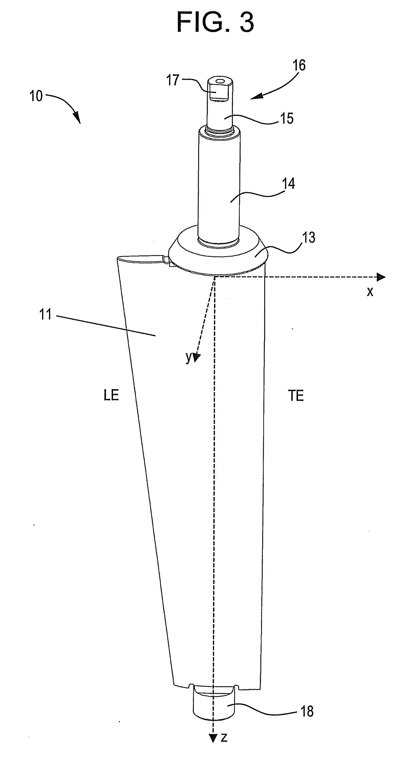
[0014]With reference to the accompanying Figures, examples of an inlet guide vane according to embodiments of the invention are disclosed. For purposes of explanation, numerous specific details are shown in the drawings and set forth in the detailed description that follows in order to provide a thorough understanding of embodiments of the invention. It will be apparent, however, that embodiments of the invention may be practiced without these specific details. In other instances, well-known structures and devices are schematically shown in order to simplify the drawing.

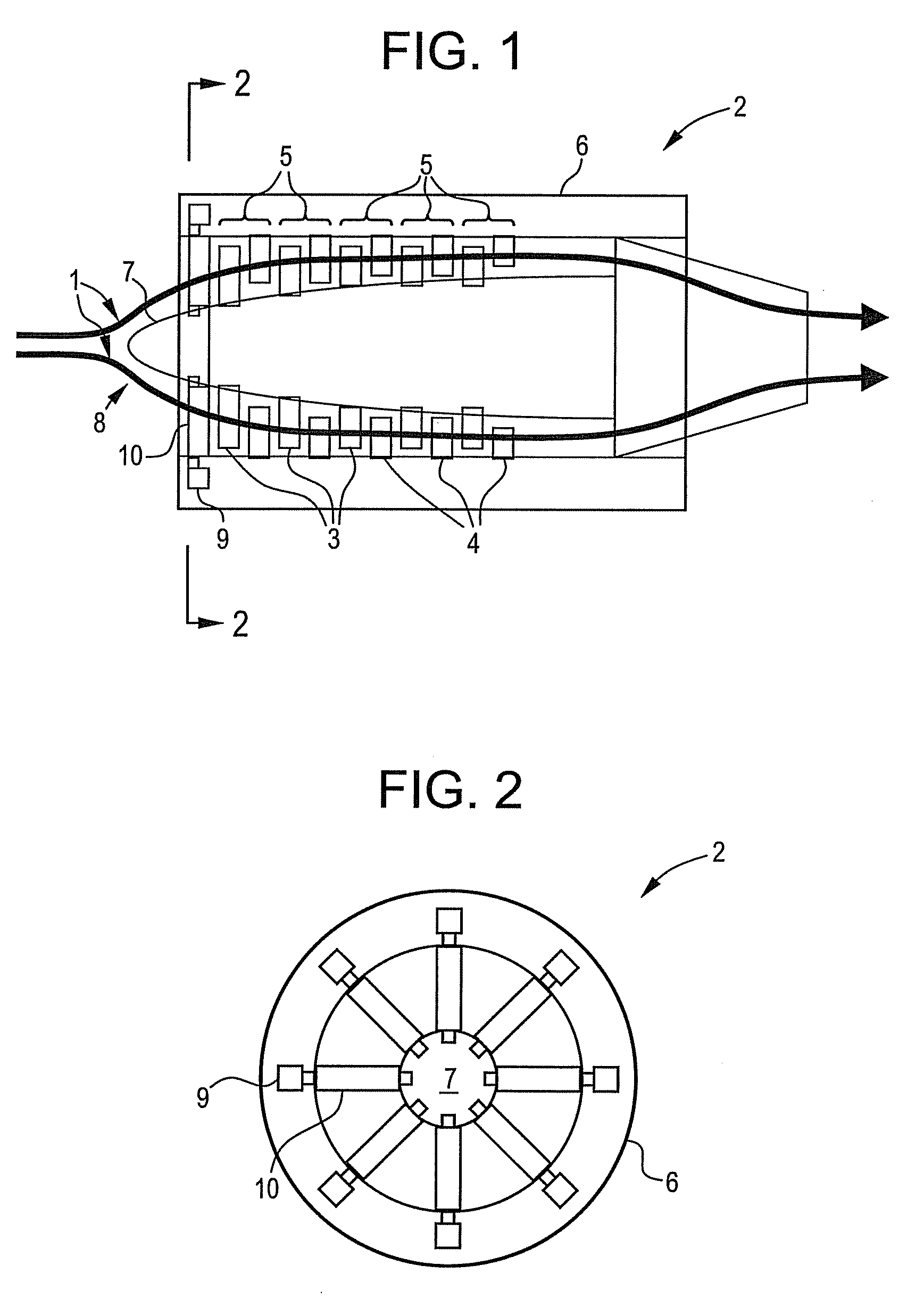
[0015]Referring now to the drawings, FIG. 1 illustrates a flow path 1 of a gas turbine 2. The gas turbine 2 includes a compressor including a plurality of airfoils such as, but not limited to, airfoils that are part of alternating rotors 3 and stators 4, each rotor / stator pair 5 comprising a stage of the compressor. The airfoils impart kinetic energy to the airflow and therefore bring about a desired flow across the ...


PUM


Abstract

An inlet guide vane having a nominal profile substantially in accordance with Cartesian coordinate values of x, y, and z set forth in TABLE 1 reduces vibration of engine components at various operating conditions. A scaling factor can be applied to the values to make the airfoil larger or smaller. The TABLE 1 x and y values are distances in inches within a tolerance which, when connected by smooth curves, define airfoil profile sections at each distance z in inches, the profile sections being joined smoothly to form a complete airfoil shape. The tolerance in an embodiment is up to about 0.16 inches.

Description

BACKGROUND[0001]Embodiments of the invention relate to airfoil profiles in gas turbines. More specifically, embodiments of the invention relate to airfoil profiles for inlet guide vanes (IGVs) of gas turbines.[0002]In gas turbines, IGVs condition flow coming into the turbine to enhance efficiency and performance. The IGVs project from the center structure of the inlet, are arranged around the circumference of the turbine inlet, span at least part of the flow path between the inlet inner barrel or center structure and inlet casing, and work in concert with the profile of the inlet itself to deliver flow having desired characteristics to the first rotor of the turbine. For example, incoming flow direction, speed, and pressure can be directed to desired values.[0003]In some gas turbines, the IGVs' angle of attack can be varied to control turbine flow rate. For example, the IGVs in some turbines are mounted on radial shafts that are rotated by actuators in the turbine housing to vary th...

Claims


Application Information

Patent Timeline
IPC IPC(8): F01D9/04F01D9/02
CPCF01D9/04F05D2250/74F01D17/162
Inventor SCHOTT, CARL GERARDBLOHM, MARC EDWARDCHALUVADI, VENKATA SIVATHERMOS, ANTHONY CONSTANTINE
Owner GENERAL ELECTRIC CO
Learn More