Tool for handling serpentine belt

a technology for handling tools and serpentine belts, which is applied in the direction of belts/chains/gearings, mechanical equipment, belts/chains/gearings, etc., can solve the problems of increasing engine load, more power consumption or failure of power transmission to vehicle components, and difficulty in reaching the serpentine belt for handling

Inactive Publication Date: 2010-03-18
CONNEELY PETER
View PDF6 Cites 4 Cited by
  • Summary
  • Abstract
  • Description
  • Claims
  • Application Information

AI Technical Summary

Problems solved by technology

Slipping off of the serpentine belt from the pulleys / idler gear leads to increase in load on the engine, more power consumption or failure in the power transmission to the components of the vehicle.
Due to this, it may be difficult to reach the serpentine belt for handling it.
Typically, a front-wheel-drive vehicle with a transversely mounted engine provides limited access to the serpentine belt, thereby necessitating lifting of the front wheel of the vehicle from the ground for accessing the serpentine belt.
Such an activity of removing the splash shield for accessing of the serpentine belt is cumbersome for an individual handling the serpentine belt.
Furthermore, in some other cases, handling of the serpentine belt is much more difficult when the engine is hot.
Due to these above mentioned reasons, just accessing the serpentine belt can be a time consuming and unpleasant experience for any individual such as an automotive specialist.
Accordingly, handling the serpentine belt by using the rod or the screwdriver may be time consuming and tiresome for an individual handling the serpentine belt.

Method used


Image

  • Tool for handling serpentine belt
  • Tool for handling serpentine belt
  • Tool for handling serpentine belt

Examples


Embodiment Construction

[0013]The exemplary embodiments described herein provide detail for illustrative purposes, and are subject to many variations in composition, structure, and design. It should be emphasized, however, that the present disclosure is not limited to a particular tool for handling the serpentine belt, as shown and described. It is understood that various omissions and substitutions of equivalents are contemplated as circumstances may suggest or render expedient, but these are intended to cover the application or implementation without departing from the spirit or scope of the claims of the present disclosure. Also, it is to be understood that the phraseology and terminology used herein are for the purpose of description and should not be regarded as limiting.

[0014]The terms “first,”“second,” and the like, herein do not denote any order, quantity, or importance, but rather are used to distinguish one element from another, and the terms “a” and “an” herein do not denote a limitation of quan...


PUM


Abstract

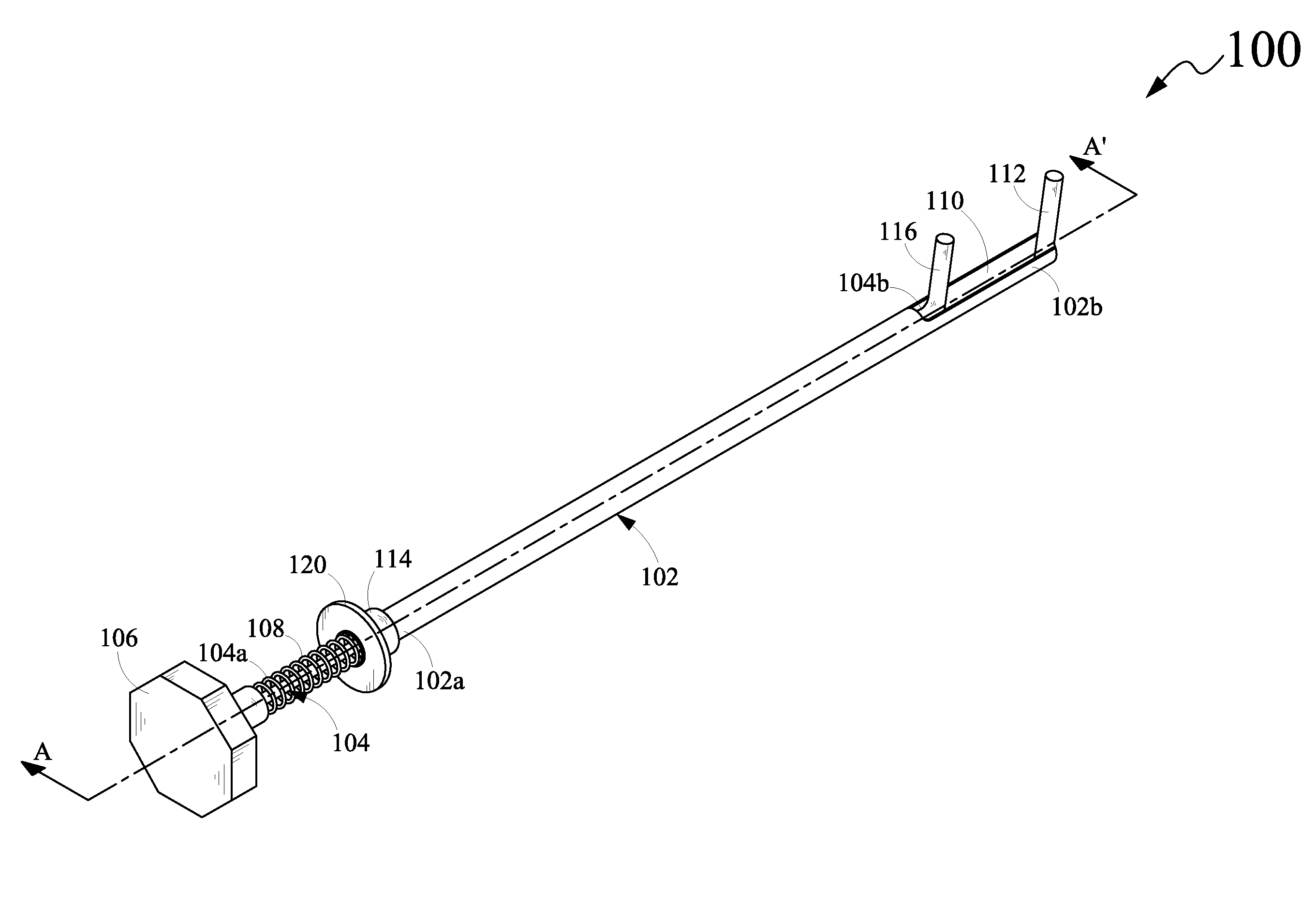
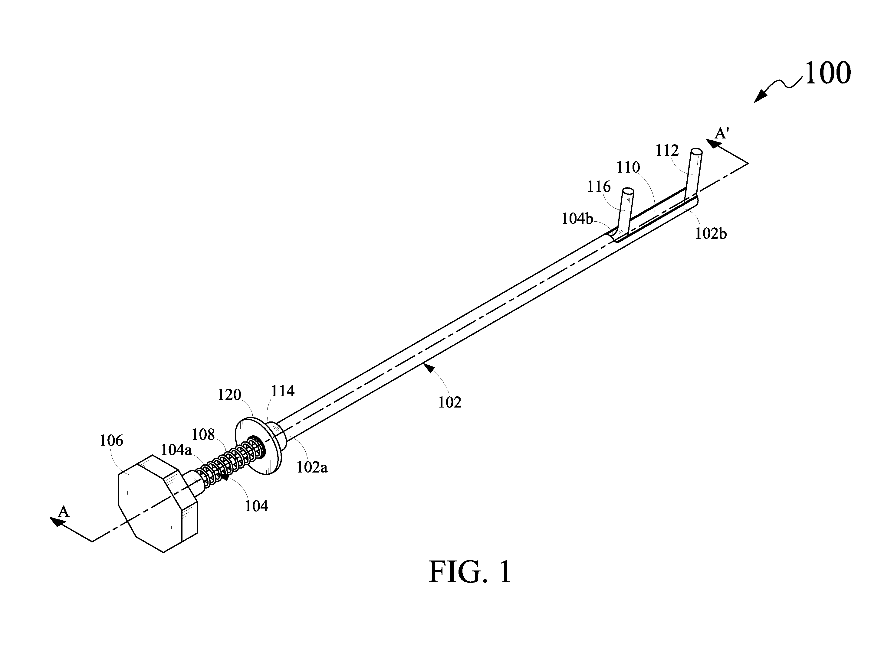
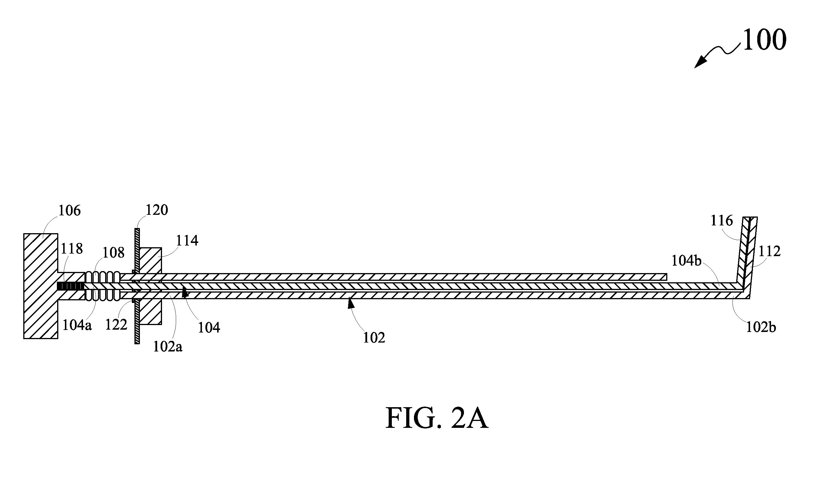
One embodiment of a tool for handling a serpentine belt may include a hollow pipe that may have a longitudinal opening configured at a distal end portion thereof. Further, the hollow pipe may include a first griping member and a sleeve member. The first gripping member may be configured at the distal end portion of the hollow pipe and may be projected outwards from the longitudinal opening. Moreover, the sleeve member may be configured at a proximal end portion of the hollow pipe. The tool may also have a rod that may be partially enclosed and slidably engaged with the hollow pipe. Further, the rod may include a second gripping member that may be configured at a distal end portion thereof in a parallel relationship with the first gripping member. The second gripping member may project outwards from the longitudinal opening. The tool may also have a handle member that may be configured at a proximal end portion of the rod. Further, the tool may have a spring member that may be disposed between the sleeve member and the handle member. The spring member may be capable of being compressed upon directing the handle member toward the sleeve member, and retracted upon releasing the handle member. Furthermore, upon directing the handle member toward the sleeve member, the second gripping member may move toward the first gripping member to hold the serpentine belt therebetween for handling the serpentine belt.

Description

CROSS REFERENCE TO RELATED APPLICATION[0001]The present disclosure claims priority under 35 United States Code, Section 119 on the U.S. Provisional Patent Application No. 61 / 096,928 filed on Sep. 15, 2008, the disclosure of which is incorporated by reference.FIELD OF THE DISCLOSURE[0002]The present disclosure relates generally to hand tools, and more particularly, to a tool for handling a serpentine belt.BACKGROUND OF THE DISCLOSURE[0003]In automotive industries, belts are used to drive various components of a vehicle. Examples of such components include power steering, alternator, water pump, AC compressor and the like. Typically, the belts transfer power from an engine of the vehicle to these components for driving them. These days, instead of employing belts individually for each of the components, a single belt is employed for driving all such components in the vehicle. Such a belt, conventionally known as a serpentine belt, routes around various pulleys and idler gears associat...

Claims


Application Information

Patent Timeline
Patent Type & Authority Applications(United States)
IPC IPC(8): F16H7/22
CPCF16H7/24
Inventor CONNEELY, PETER
Owner CONNEELY PETER
Why Eureka
Try Eureka