Camera body

a technology of camera body and lens body, which is applied in the field of camera body, can solve the problems of difficult to reduce the size of the camera body with an interchangeable lens digital camera, and achieve the effect of not affecting the accuracy of video autofocus

Inactive Publication Date: 2010-03-25
PANASONIC CORP
View PDF10 Cites 18 Cited by
  • Summary
  • Abstract
  • Description
  • Claims
  • Application Information

AI Technical Summary

Benefits of technology

[0009]With this camera body, when the camera controller decides that auxiliary light is used, and the camera controller decides that the flash device mounted to the hot shoe includes an external auxiliary light source arranged to emit near infrared light, the imaging element and the flash device are controlled by the camera controller so that the image data is acquired while the external main light source of the flash device intermittently emits light during the video autofocusing. Accordingly, even when a flash device including an external auxiliary light source arranged to emit near infrared light is mounted to the camera body, an external main light source can be used to perform video autofocusing, and there will be no decrease in the accuracy of video autofocusing even with a flash device that is not compatible with video autofocusing. In other words, with this camera body it is possible to ensure interchangeability with various flash devices.

Problems solved by technology

However, it is difficult to reduce the size of the camera body with an interchangeable lens digital camera of this type because the camera body is equipped with a mirror box device.

Method used


Image

  • Camera body
  • Camera body
  • Camera body

Examples


first embodiment

[0030]1: Configuration

[0031]1-1: Overview of Digital Camera

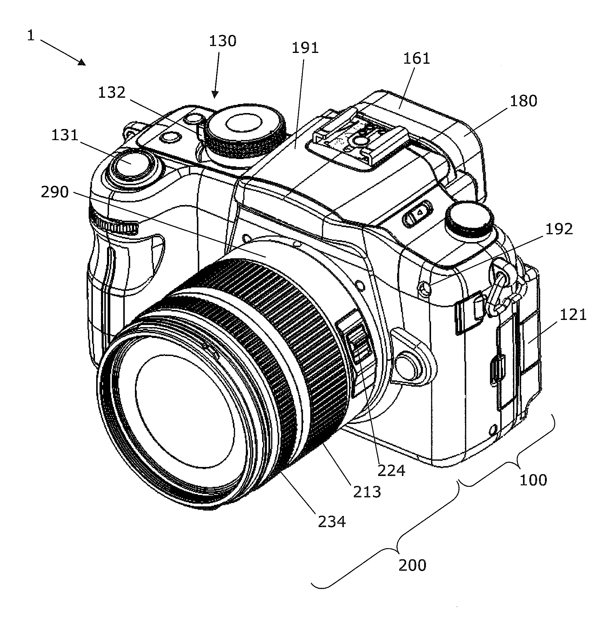
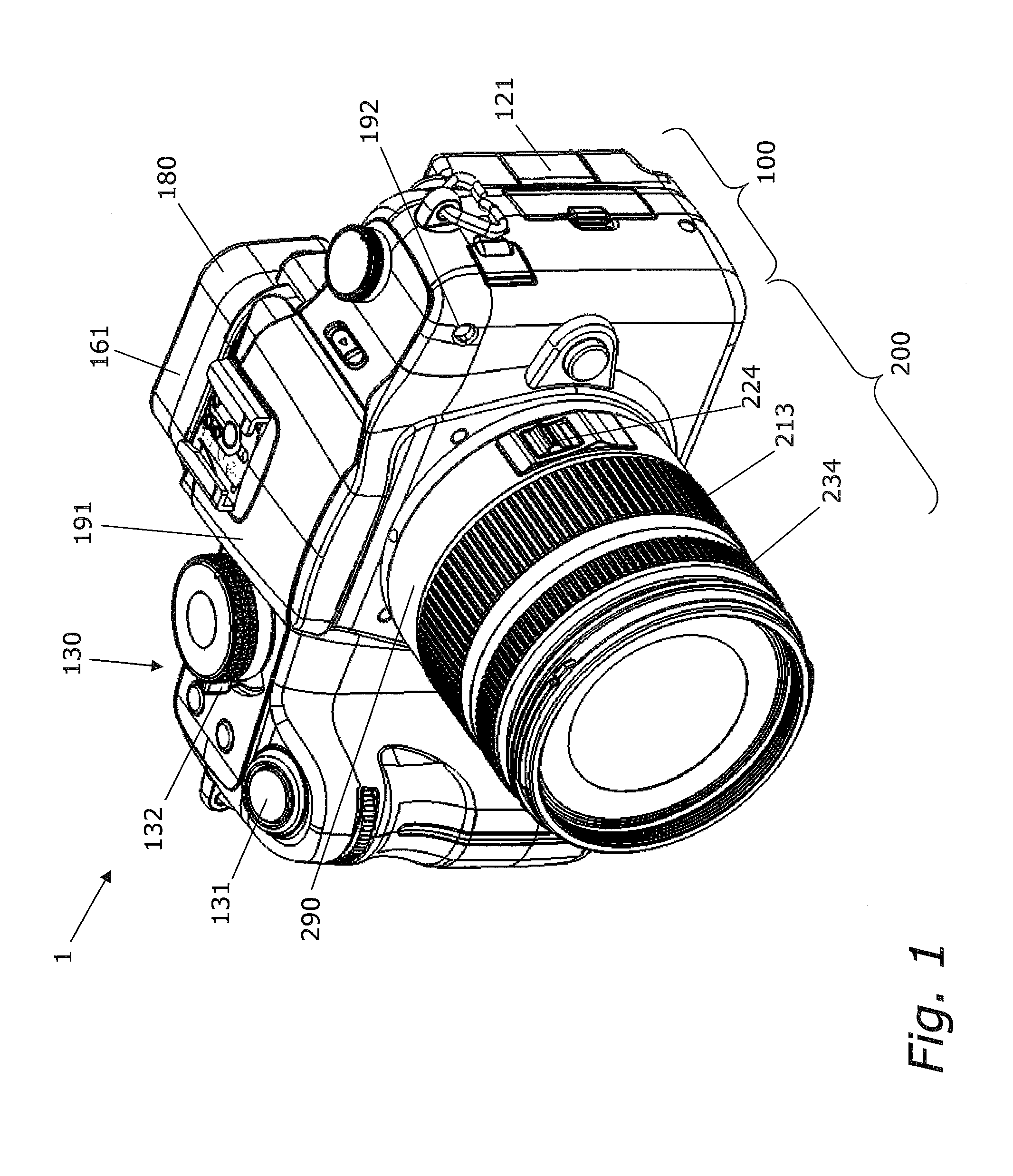
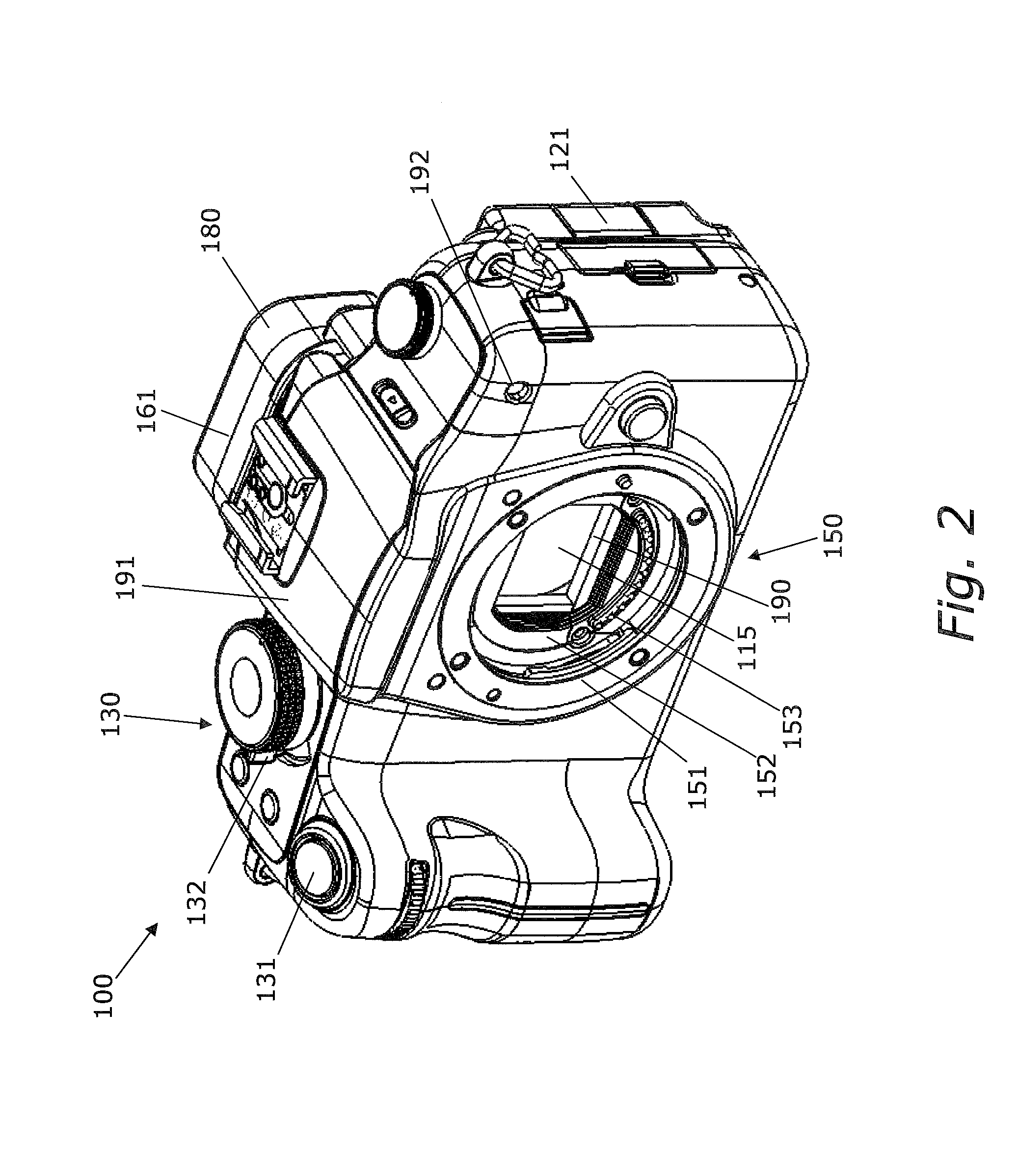
[0032]As shown in FIGS. 1 to 3, a digital camera 1 according to the first embodiment comprises a camera body 100 and a lens unit 200 that can be mounted to the camera body 100.

[0033]Unlike with a single lens reflex camera, the camera body 100 has no mirror box device, so its flange-back is smaller than that of a single lens reflex camera. Reducing the flange-back also allows the camera body 100 to be made more compact. Furthermore, reducing the flange-back affords greater latitude in design of the optical system, so the lens unit 200 can be made more compact.

[0034]For the sake of convenience in the following description, the subject side of the digital camera 1 will be referred to as the front, the opposite side of the digital camera 1 from the subject as the rear or back, the vertical upper side when the digital camera 1 is in its normal orientation (hereinafter also referred to as landscape orientation) as the top, and the...

second embodiment

[0136]The following description will focus on differences from the camera body 100 in the first embodiment, and portions that are shared with the first embodiment will not be described again. Also, components that have substantially the same function as in the first embodiment will be numbered the same. The camera body 100 according to the second embodiment differs from the camera body 100 of the first embodiment in its operation when an external flash that is not compatible with video autofocusing is mounted. The rest of the configuration is the same as that in the first embodiment.

[0137]FIG. 12 is a flowchart related to the use of auxiliary light during video autofocusing in a second embodiment. The operation from step S01 to step S07 is the same as in the first embodiment.

[0138]As shown in FIG. 12, if it is decided that the external flash is not compatible with video autofocusing (No in step S06), such as when the external flash 400 is mounted to the hot shoe 161, the camera cont...

third embodiment

[0143]The following description will focus on differences from the camera body 100 in the first embodiment, and portions that are shared with the first embodiment will not be described again. Also, components that have substantially the same function as in the first embodiment will be numbered the same. The camera body 100 according to the third embodiment differs from the camera body 100 of the first embodiment in its operation when an external flash that is not compatible with video autofocusing is mounted. The rest of the configuration is the same as that in the first embodiment.

[0144]FIG. 13 is a flowchart related to the use of auxiliary light during video autofocusing in a third embodiment. The operation from step S01 to step S07 is the same as in the first embodiment.

[0145]As shown in FIG. 13, if it is decided to use auxiliary light, and the external flash decision part 145 decides that the external flash is not compatible with video autofocusing (No in step S06), the light em...


PUM


Abstract

A camera body includes an imaging element, a hot shoe, and a camera controller. The imaging element is configured to convert an optical image of the subject into an electrical signal, and is configured to produce image data about the subject. The hot shoe allows the flash device to be mounted. The camera controller is configured to calculate an evaluation value on the basis of the image data produced by the imaging element, and is configured to perform video autofocusing on the basis of this evaluation value. The camera controller is configured to control the imaging element and the flash device so that when the camera controller decides that auxiliary light is needed, and the camera controller decides that the external auxiliary light source of the flash device mounted to the hot shoe is not compatible with video autofocusing, the image data is acquired while an external main light source of the flash device intermittently emits light during the video autofocusing.

Description

CROSS-REFERENCE TO RELATED APPLICATIONS[0001]This application claims priority to Japanese Patent Application No. 2008-240478 filed on Sep. 19, 2008. The entire disclosure of Japanese Patent Application No. 2008-240478 is hereby incorporated herein by reference.TECHNICAL FIELD[0002]The technology disclosed herein relates to a camera body to which an external flash device can be mounted.DESCRIPTION OF THE RELATED ART[0003]Japanese Laid-Open Patent Application 2007-127836 discloses a single lens reflex camera. This camera has a lens unit and a camera body. The camera body is equipped with a CCD (Charge Coupled Device) image sensor, and a mirror box device disposed between the lens unit and the CCD image sensor. The mirror box device guides the subject light flux from the lens unit to either the CCD image sensor or a prism. The subject light flux guided to the prism is guided by the prism to a viewfinder.SUMMARY[0004]However, it is difficult to reduce the size of the camera body with an...

Claims


Application Information

Patent Timeline
Patent Type & Authority Applications(United States)
IPC IPC(8): H04N5/228H04N5/232H04N5/225
CPCG03B17/14H04N5/2354H04N5/23212H04N5/23209H04N23/663H04N23/672H04N23/673H04N23/74
Inventor HONJO, KENICHIMIYAZAKI, KYOICHI
Owner PANASONIC CORP
Why Eureka
Try Eureka