Atomic absorption spectrophotometer

a spectrophotometer and atomic absorption technology, applied in the field ofatomic absorption spectrophotometers, can solve problems such as the decrease of conversion accuracy, and achieve the effect of accurate and efficient atomic absorption spectroscopic analysis and shortening the lamp's li

Active Publication Date: 2010-03-25
SHIMADZU CORP
View PDF2 Cites 6 Cited by
  • Summary
  • Abstract
  • Description
  • Claims
  • Application Information

AI Technical Summary

Benefits of technology

[0018]In each of the atomic absorption spectrophotometers according to the first and second aspects of the present invention, the amounts of light from the light sources (i.e. the hollow cathode lamp and deuterium lamp) are almost equalized by the function of each aforementioned means. This equalization of the amounts of light from plural lamps (or light sources) has advantages such as: it can be applied to a variety of lamps, it has a good S / N, and it functions without unsteadying the lamp's amount of light and shortening the lamp's lifetime. Therefore, it is possible to perform an accurate and efficient atomic absorption spectroscopic analysis.

Problems solved by technology

Hence, the conversion accuracy decreases in the case where the signal is excessively small.

Method used


Image

  • Atomic absorption spectrophotometer
  • Atomic absorption spectrophotometer
  • Atomic absorption spectrophotometer

Examples


embodiments

First Embodiment

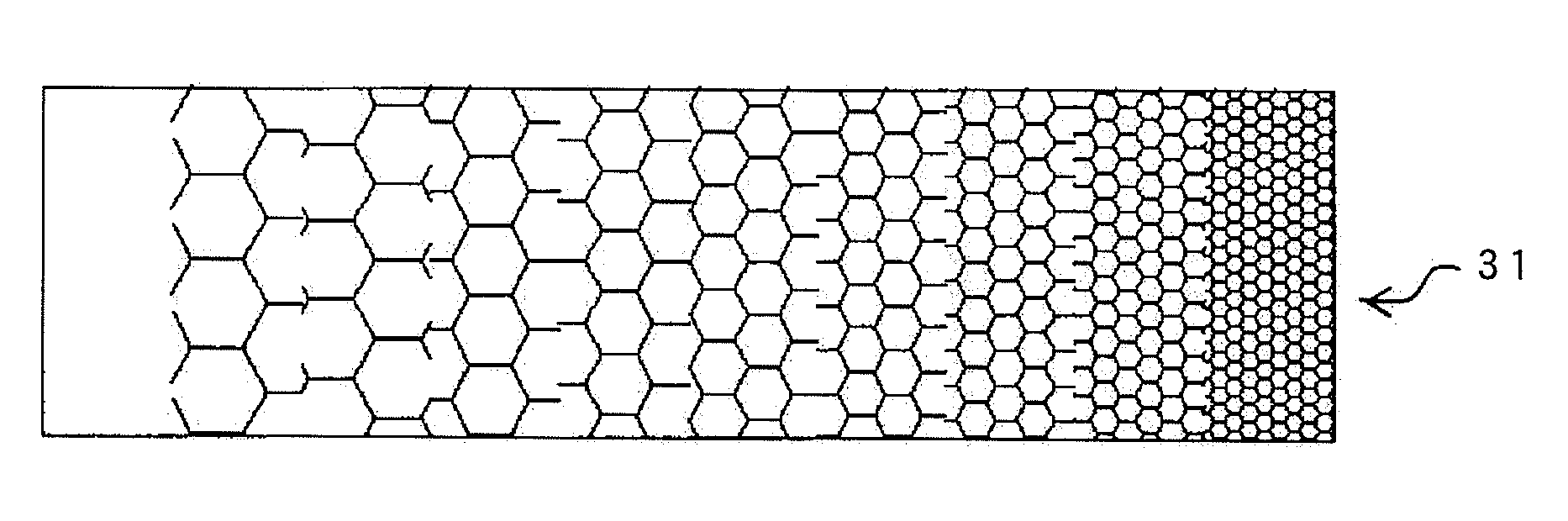
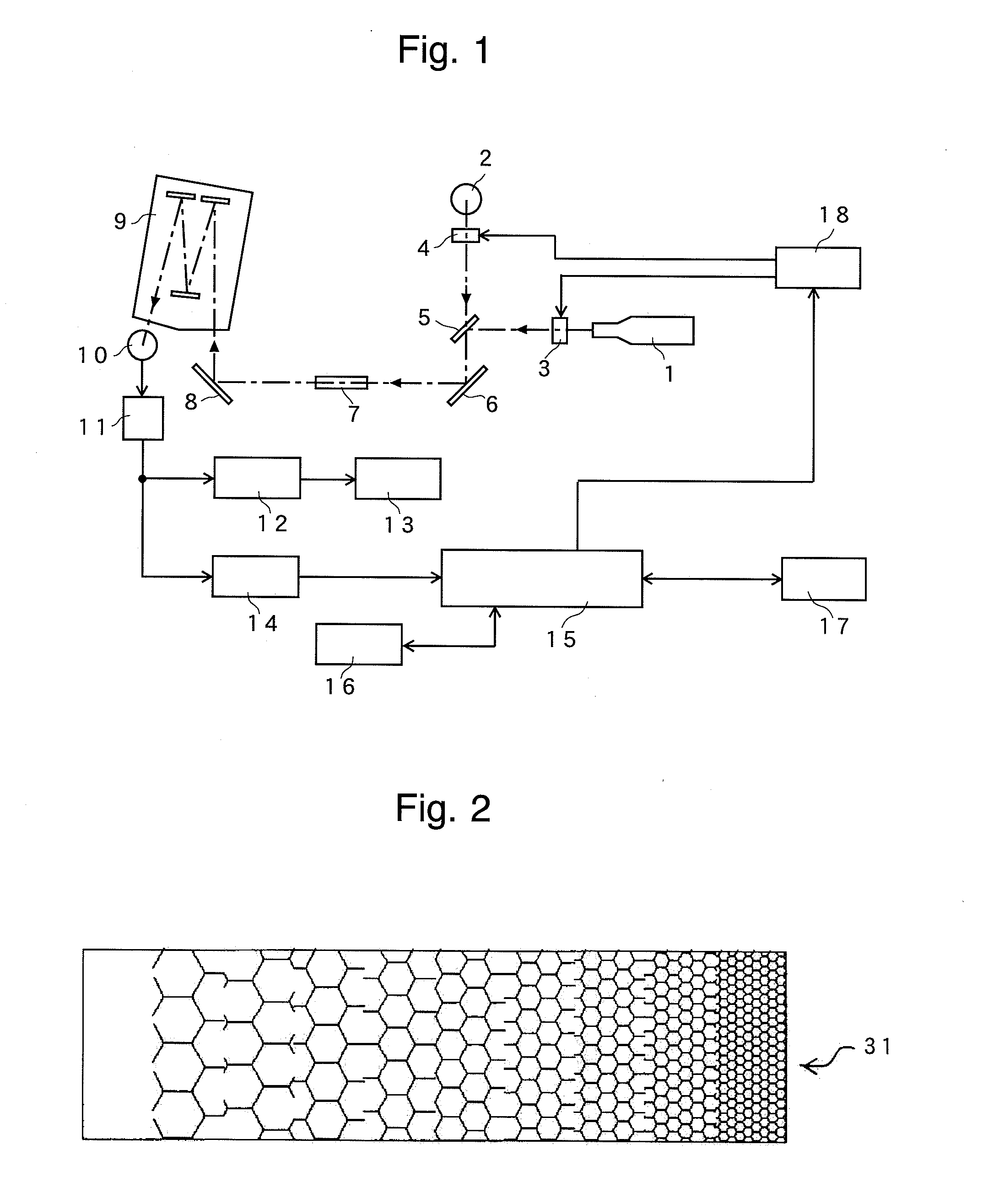
[0054]An atomic absorption spectrophotometer according to an embodiment (the first embodiment) of the present invention will be described with reference to FIGS. 1 and 2. FIG. 1 is a schematic configuration diagram of the atomic absorption spectrophotometer of the first embodiment. FIG. 2 is a diagram roughly illustrating the optical filter mounted in the dimmer apparatus in the atomic absorption spectrophotometer of the first embodiment.

[0055]In FIG. 1, a first light source 1 is composed of a hollow cathode lamp and intermittently turned on, for example, at 60 Hz. A second light source 2 is composed of a deuterium lamp and intermittently turned on so that it should be lighted while the first light source 1 is not lighted. A first dimmer apparatus 3 is placed between the first light source 1 and a beam combiner 5, and a second dimmer apparatus 4 is placed between the second light source 2 and the beam combiner 5.

[0056]A light beam emitted from the first light source ...

second embodiment

[0067]Next, an atomic absorption spectrophotometer according to another embodiment (the second embodiment) of the present invention will be described with reference to FIGS. 7 and 8. FIG. 7 is a schematic configuration diagram of the atomic absorption spectrophotometer of the second embodiment. FIG. 8 is a diagram roughly illustrating a light attenuator 20 in the atomic absorption spectrophotometer of the second embodiment. The same or corresponding components as in the first embodiment are indicated with the same numerals and the detailed explanations are omitted.

[0068]In the configuration of the second embodiment, a dimmer apparatus 4 which corresponds to the second dimmer apparatus 4 in the first embodiment includes: a light attenuator 20 placed on the light beam path between a second light source 2, which is a deuterium lamp, and a beam combiner 5; and a drive mechanism 19 composed of a rack, a pinion, and a stepping motor for laterally moving the light attenuator 20. The light ...


PUM

PropertyMeasurementUnit
flat wavelength absorptionaaaaaaaaaa
areaaaaaaaaaaa
wavelength rangeaaaaaaaaaa

Abstract

With the measurement unit (7) empty and with the maximum (or approximately 100%) transmissivity of the first dimmer apparatus (3) and the second dimmer apparatus (4), the output voltages of the preamplifier (11) (i.e. the value Pa corresponding to the first light source 1 and the value Pb corresponding to the second light source 2) are stored in the memory unit (16). The appropriate transmissivity computation unit (17) compares the Pa value with the Pb values, sets the smaller value as Ps, and computes the appropriate transmissivity (Ps/Pa)×100 of the dimmer apparatus (3) and the appropriate transmissivity (Ps/Pb)×100 of the dimmer apparatus (4). The controller (15) sets the transmissivities of the dimmer apparatus (3) and the dimmer apparatus (4) to have the previously obtained respective appropriate transmissivities. As a result, both the output voltages (or the values corresponding to the first light source (1) and second light source (2)) of the preamplifier (11) become Ps. The value of Ps is optimized by changing the sensitivity of the photoelectric detector (10). Accordingly, it is possible to equalize the amounts of light of plural lamps (or light sources) simultaneously used, without deteriorating the S/N, unsteadying the lamp's amount of light, and shortening the lamp's lifetime.

Description

TECHNICAL FIELD[0001]The present invention relates to an atomic absorption spectrophotometer. More specifically, it relates to an atomic absorption spectrophotometer in which a plurality of light sources, such as a hollow cathode lamp and deuterium lamp, are simultaneously used.BACKGROUND ART[0002]One type of atomic absorption spectrophotometers in which a plurality of light sources are used has, for example, a function for correcting background absorption with a hollow cathode lamp and deuterium lamp. In such an apparatus, a light beam provided from the hollow cathode lamp and a light beam provided from the deuterium lamp are combined by a beam combiner for example, pass through the space where an analysis sample solution is sprayed (globulized) and atomized, and then are introduced into a spectroscope to become a light beam of necessary wavelength range. After that, the light enters a photoelectric detector to be converted into an electric signal proportional to the light intensit...

Claims


Application Information

Patent Timeline
Patent Type & Authority Applications(United States)
IPC IPC(8): G01N21/31G01J3/30
CPCG01N21/274G01N21/3151G01N21/3103
Inventor HARADA, KATSUMISUGIHARA, KAZUO
Owner SHIMADZU CORP
Why Eureka
Try Eureka