

Thermally assisted magnetic head having an asymmetric plasmon antenna and manufacturing method thereof
a technology of plasmon antenna and magnetic head, which is applied in the direction of instruments, arms with optical waveguides, data recording, etc., can solve the problems of reducing affecting the coercitivity of recording medium, and reducing the volume of particles, so as to achieve accurate control of the amount of etching
Active Publication Date: 2010-03-25
TDK CORPARATION
View PDF15 Cites 42 Cited by
- Summary
- Abstract
- Description
- Claims
- Application Information
AI Technical Summary
Benefits of technology
[0020]As a result of diligent research, the inventors found that near-field light emission intensity generated in the vicinity of the sharpest first corner strengthens, while near-field light emission intensity generated in the vicinity of the second and third corners becomes relatively weak, when the first, second and third corners of the plasmon antenna, as viewed from a direction perpendicular to the medium-facing surface, satisfy the relationship α<β, α<γ and β≠γ. Therefore, the present invention affords a method for manufacturing a thermally assisted magnetic head comprising a plasm
Problems solved by technology
Reducing the size of magnetic microparticles, however, is problematic in that reduction in particle volume is accompanied by a drop in magnetization thermal stability.
Making the magnetic microparticles smaller implies reducing their volume V. In turn, this makes KUV/kBT smaller, thereby impairing thermal stability.
An approach for addressing this problem is increasing KU commensurately, but doing so results in a larger coercitivity of the recording medium.
Thus, writing may beco
Method used
View moreImage
Smart ImageViewing Examples

Examples
 PUM
 Abstract
A thermally assisted magnetic head according to the present invention includes: a medium-facing surface, a main magnetic pole provided on the medium-facing surface, and a plasmon antenna provided on the medium-facing surface in the vicinity of the main magnetic pole, wherein the plasmon antenna is shaped as a triangular flat plate having first, second and third corners, such that the distance from the first corner to the main magnetic pole is shorter than the distance from the second corner to the main magnetic pole and the distance from the third corner to the main magnetic pole, and the interior angle α of the first corner, the interior angle β of the second corner and the interior angle γ of the third corner satisfy relationships α<β, α<γ and β≠γ.
Description
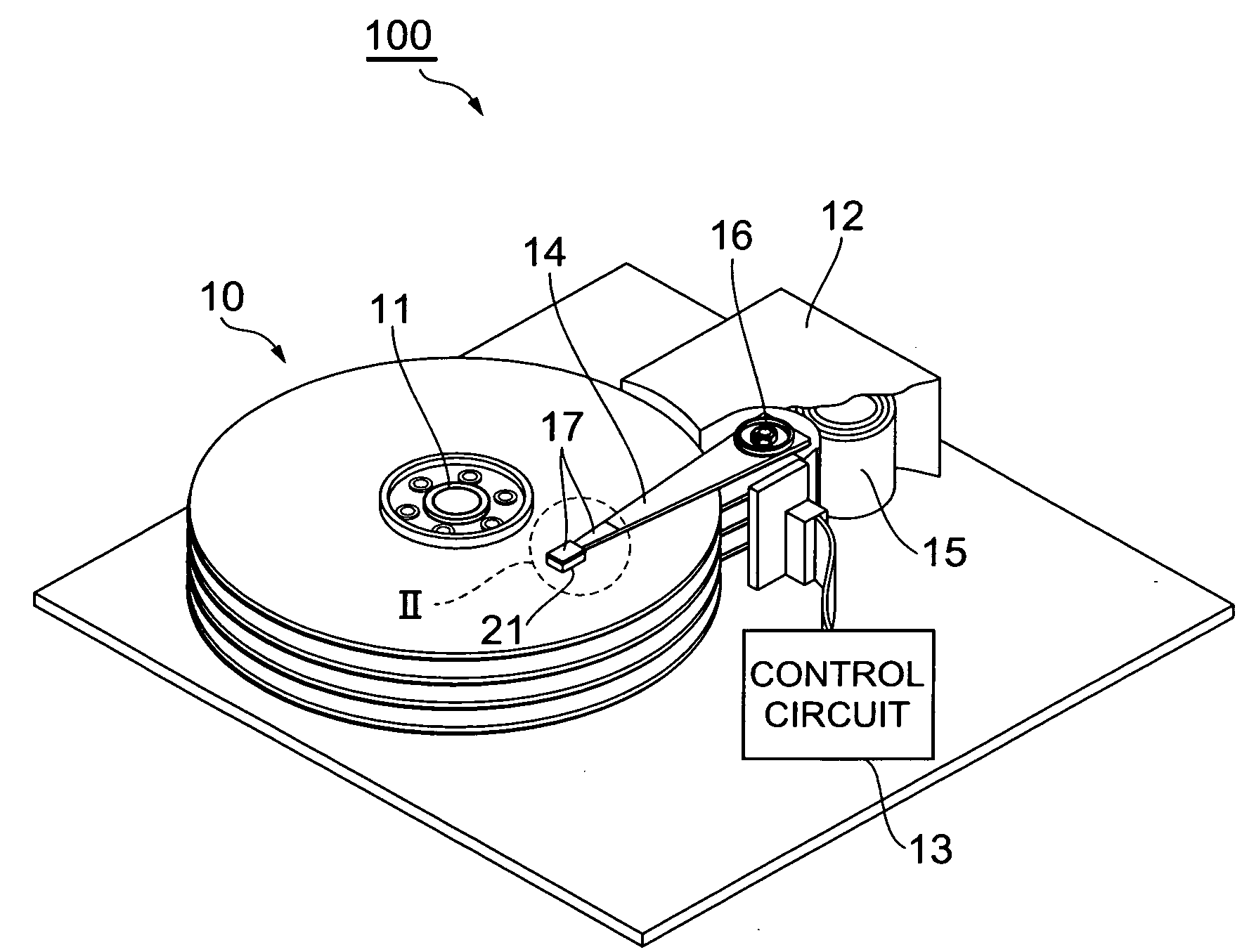
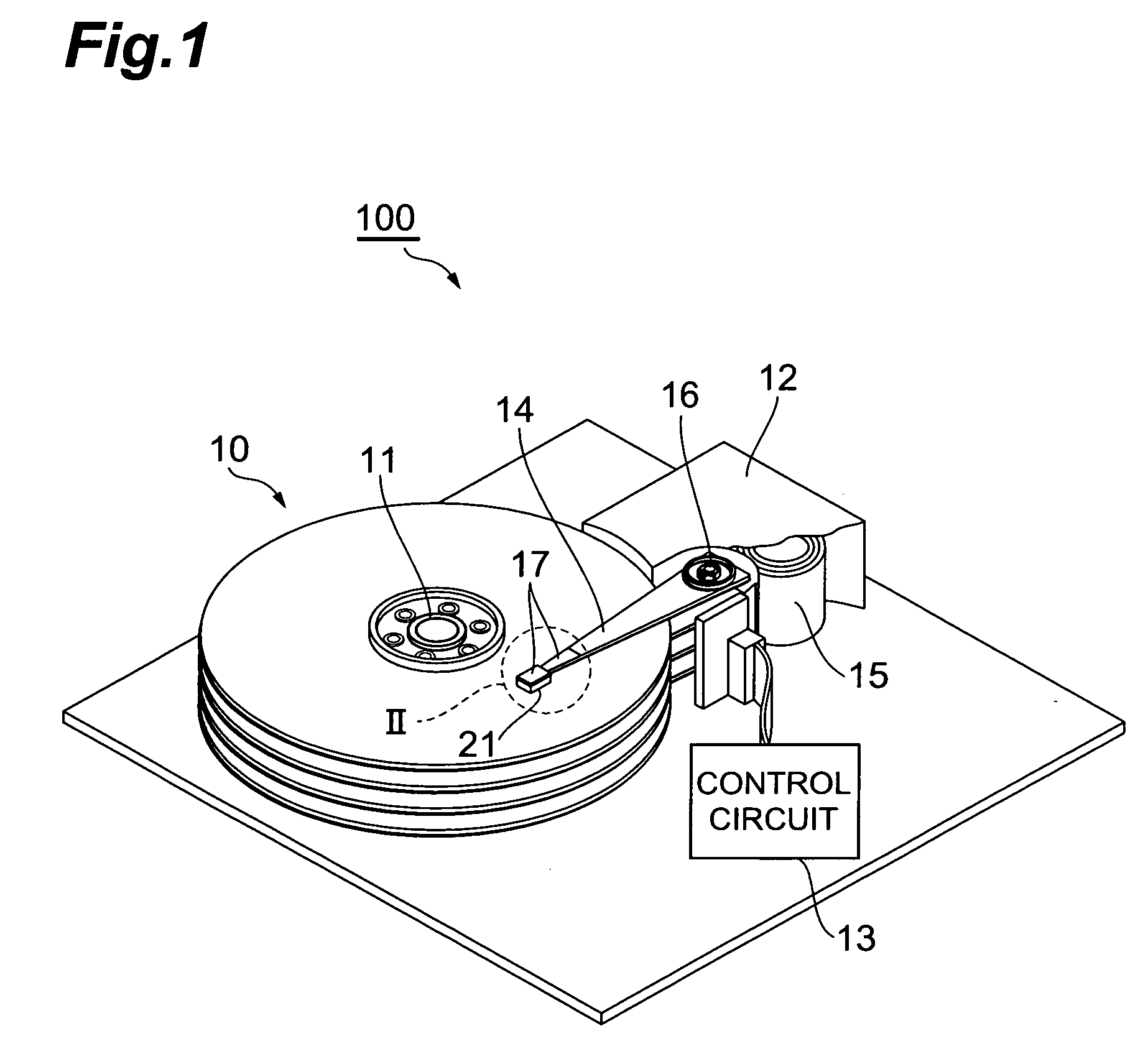
BACKGROUND OF THE INVENTION[0001]1. Field of the Invention[0002]The present invention relates to a thermally assisted magnetic head having an asymmetric plasmon antenna, a head gimbal assembly and a hard disk drive, and to a method for manufacturing the thermally assisted magnetic head having an asymmetric plasmon antenna.[0003]2. Related Background Art[0004]Thin-film magnetic heads must deliver ever greater performance to cope with higher recording densities in hard disk drives. Widely used thin-film magnetic heads include composite thin-film magnetic heads having a multilayer structure comprising, for instance, a magnetic sensing element such as a magnetoresistive (MR) effect element and an electromagnetic coil element. These elements write and read data signals to / from a magnetic disk, which is a magnetic recording medium.[0005]The magnetic recording medium is normally a so-called discontinuous medium having a structure in which magnetic microparticles are aggregated, each magnet...
Claims
Login to View More Application Information
Patent Timeline
 IPC IPC(8): G11B5/02G11B5/127
CPCG11B5/314G11B2005/0021G11B2005/001G11B5/4866
InventorKOMURA, EIJITAKAYAMA, SEIICHITOMIKAWA, SATOSHITANAKA, KOSUKESHIMAZAWA, KOJI
OwnerTDK CORPARATION