3D geometric modeling and 3D video content creation

a technology of geometric modeling and 3d video content, applied in the field of three dimensional imaging and depth measurement of objects, can solve the problems of inherently inferior accuracy and resolution to that obtained in triangulation methods, automatic correspondence algorithms often contain an abundance of errors in matching shots from different cameras, and are not error-prone and non-robus

Active Publication Date: 2010-03-25
MANTIS VISION
View PDF79 Cites 422 Cited by
  • Summary
  • Abstract
  • Description
  • Claims
  • Application Information

AI Technical Summary

Benefits of technology

[0192]extracting from said resultant image one or more of the following: at least one maximum element, at least one minimum element and at least one saddle element, and extracting their locations respective to said epipolar lines in said resultant image.
[0193]According to an embodiment of the present invention, the method further comprises determining the corresponding feature types by determining their locations and/or by determining values of the one or more of the following: at least one maximum element, at least one mi...

Problems solved by technology

Such a method is dependent on the imaged surfaces being highly textured and therefore error prone and non-robust.
Furthermore, automatic correspondence algorithms often contain an abundance of errors in matching between shots from different cameras.
Such methods, referred to as time-of-flight, are generally immune to occlusions typical of triangulation methods, but the accuracy and resolution are inherently inferior to that obtained in triangulation methods.
The very fact that hundreds of methods and systems exist today hints at the underlying problem of a lack of a sufficiently effective and reliable method for 3D imaging.
Furthermore, most of the systems that utilize active triangulation methods today are restricted to non dy...

Method used


Image

  • 3D geometric modeling and 3D video content creation
  • 3D geometric modeling and 3D video content creation
  • 3D geometric modeling and 3D video content creation

Examples


Embodiment Construction

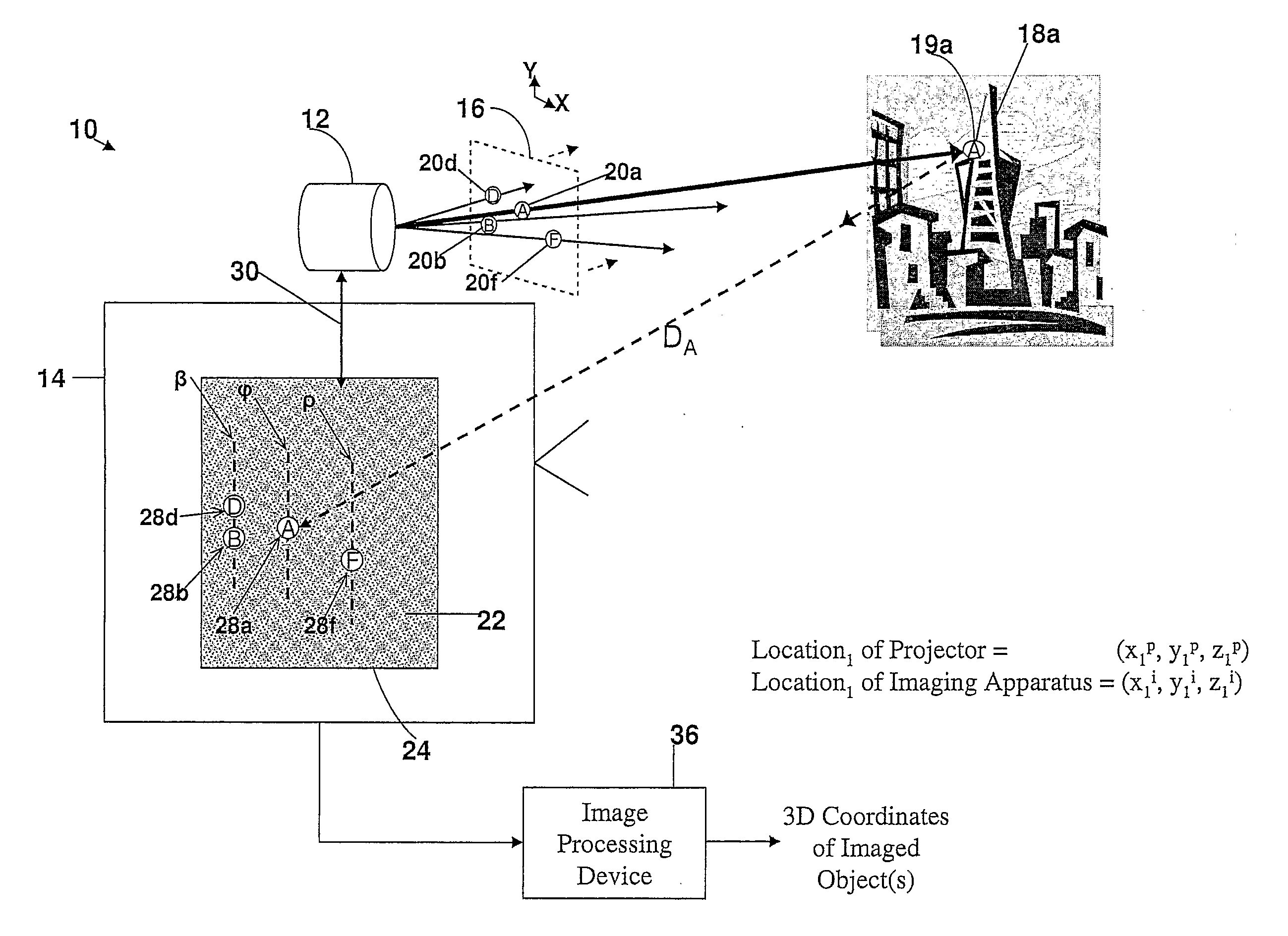
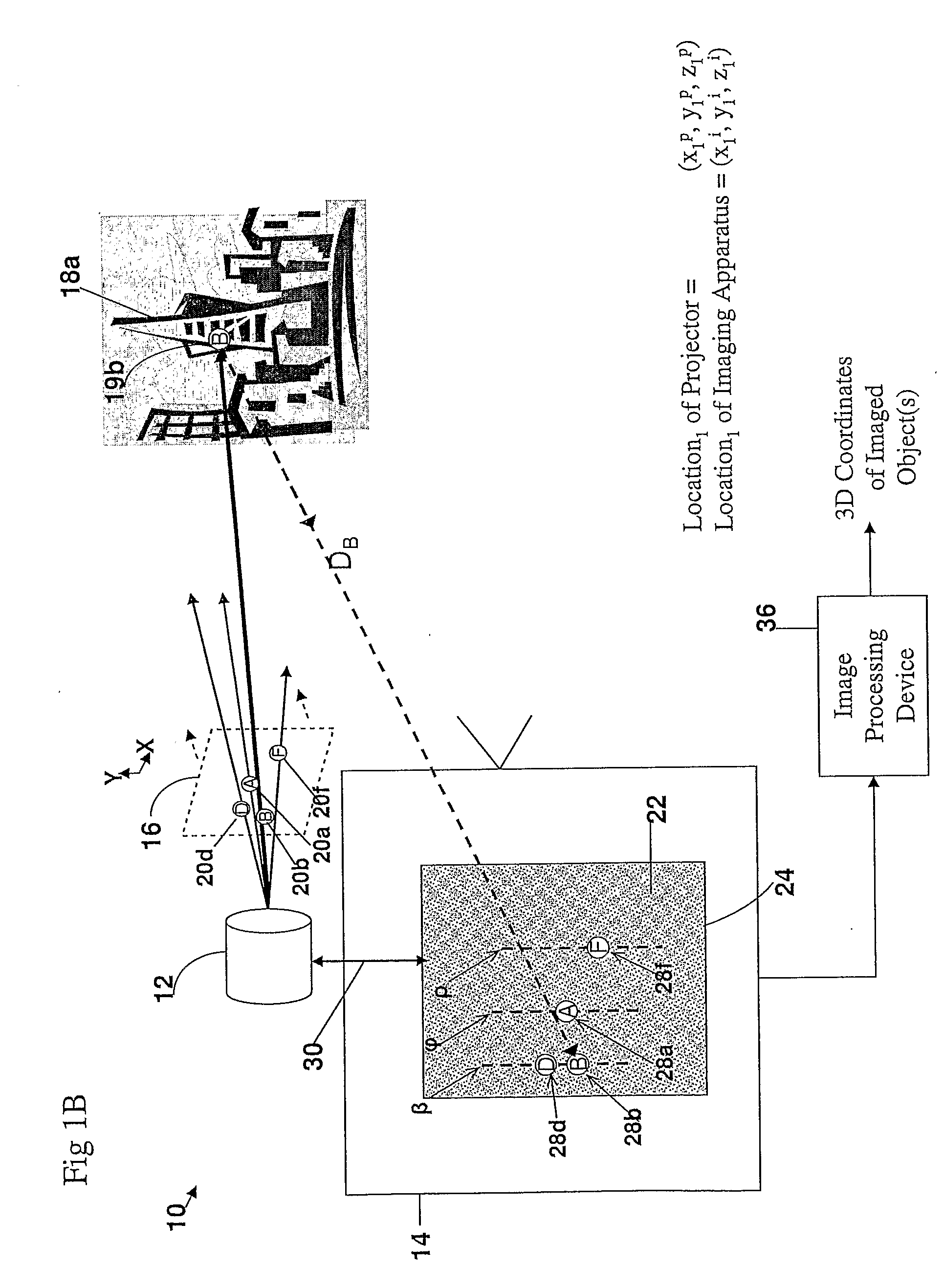
[0281]The present embodiments provide an apparatus and a method for three dimensional imaging of static and moving objects. In particular, it is possible to determine three-dimensional spatial shape data of a given object(s) by (a) projecting an encoded bi-dimensional light pattern on the object(s); and (b) analyzing a 2D image of the reflected bi-dimensional light pattern utilizing the optical constraints and principles associated with epipolar geometry and triangulation.

[0282]The principles and operation of an apparatus and method according to the present invention may be better understood with reference to the drawings and accompanying description.

[0283]Before explaining at least one embodiment of the invention in detail, it is to be understood that the invention is not limited in its application to the details of construction and the arrangement of the components set forth in the following description or illustrated in the drawings. The invention is capable of other embodiments ...


PUM


Abstract

A system, apparatus and method of obtaining data from a 2D image in order to determine the 3D shape of objects appearing in said 2D image, said 2D image having distinguishable epipolar lines, said method comprising: (a) providing a predefined set of types of features, giving rise to feature types, each feature type being distinguishable according to a unique bi-dimensional formation; (b) providing a coded light pattern comprising multiple appearances of said feature types; (c) projecting said coded light pattern on said objects such that the distance between epipolar lines associated with substantially identical features is less than the distance between corresponding locations of two neighboring features; (d) capturing a 2D image of said objects having said projected coded light pattern projected thereupon, said 2D image comprising reflected said feature types; and (e) extracting: (i) said reflected feature types according to the unique bi-dimensional formations; and (ii) locations of said reflected feature types on respective said epipolar lines in said 2D image.

Description

RELATIONSHIP TO EXISTING APPLICATIONS[0001]The present application claims priority from U.S. provisional patent 60 / 860,209 filed on Nov. 21, 2006, the contents of which are hereby incorporated by reference.[0002]The present application also claims priority from U.S. provisional patent 60 / 907,495 filed on Apr. 4, 2007, the contents of which are hereby incorporated by reference.[0003]The present application also claims priority from U.S. provisional patent 60 / 924,206 filed on May 3, 2007, the contents of which are hereby incorporated by reference.[0004]The present application also claims priority from U.S. provisional patent 60 / 929,835 filed on Jul. 13, 2007, the contents of which are hereby incorporated by reference.[0005]The present application also claims priority from U.S. provisional patent 60 / 935,427 filed on Aug. 13, 2007, the contents of which are hereby incorporated by reference.FIELD AND BACKGROUND OF THE INVENTION[0006]The present invention relates to a system and a method ...

Claims


Application Information

Patent Timeline
IPC IPC(8): G06K9/46G06V10/145
CPCG01B11/25G01C11/025G06T7/0057G06K9/2036G06T7/521G06T7/536G06V10/145G01B11/2513G06T15/205G06T2200/04G06T2207/20228
Inventor GORDON, EYALBITTAN, GUR ARIEH
Owner MANTIS VISION
Why Eureka
Try Eureka