Fluid transporting device, and fluid transporter

a technology of fluid transporting device and fluid transporter, which is applied in the direction of positive displacement liquid engine, intravenous device, machine/engine, etc., can solve the problems of difficult thickness reduction, difficult to keep the flow rate steady, and difficult to reduce size, so as to reduce the driving force of the rotary disc, stable fluid rate, and reduce frictional resistance

Inactive Publication Date: 2010-03-25
SEIKO EPSON CORP
View PDF36 Cites 23 Cited by
  • Summary
  • Abstract
  • Description
  • Claims
  • Application Information

AI Technical Summary

Benefits of technology

[0010]According to this invention, the tube is pressed substantially at right angles by the push pins so that the tube is hardly stretched so that the internal diameter (or the fluid feeding portion) of the tube does not vary, so that a stable fluid rate can be obtained.
[0011]Because of the structure for the rotary pressure mechanism to push the push pins, moreover, the flow rate can be freely adjusted by setting the number and stroke of the push pins arbitrarily. It is, therefore, possible to provide a fluid transporting device of a desired flow rate easily.
[0012]The rollers are rotated backward of the rotating direction of the rotary disc by the frictional force between the roller and the push pin. As a result, the frictional resistance can be lowered to reduce the driving force of the rotary disc. The torque to be generated by a motor acting as the drive source of the rotary disc may be low, as will be described in detail in the later-described modes of embodiment, so that the size reduction can be made to reduce the size of the fluid transporting device.
[0015]Even when the operation is interrupted, moreover, the tube is closed at its one portion so that the fluid can be prevented from flowing out. This can enhance the safety, in case the fluid is such one of chemicals that its safety has to be considered.
[0017]The fluid transporting device of the aforementioned structure is adopted according to this invention, so that the aforementioned effects can be obtained. At the same time, the fluid transporting device and fluid storing container are made to communicate by the tube. As a result, the fluid storing container can be easily replaced so that its handling is facilitated and so that the fluid transporting device can be repeatedly used for economic effects.
[0019]According to this structure, the fluid transporting device and the fluid storing container are arranged not to overlap so that they can be reduced in size. Moreover, the casings for the fluid transporting device and the fluid storing container can be made single to reduce the cost.

Problems solved by technology

It is, therefore, thought that the fluid feeding portion of the tube (or the internal diameter of the tube) is varied from the initial size as a result that the tube is stretched in the rotating direction of the rotor, so that the fluid flow rate changes thereby to make it difficult to keep the flow rate stably.
Moreover, the aforementioned first prior art is constituted such that the housing includes the fluid transporting device, a drive control circuit, a display unit and a control unit, thereby to make the size reduction difficult.
On the other hand, the aforementioned second prior art is constituted such that the motor module is laid over the roller unit, thereby to raise a problem that the thickness reduction is difficult.

Method used


Image

  • Fluid transporting device, and fluid transporter
  • Fluid transporting device, and fluid transporter
  • Fluid transporting device, and fluid transporter

Examples


embodiment 1

[0031]At first, the description is made on Mode of Embodiment 1 of the invention.

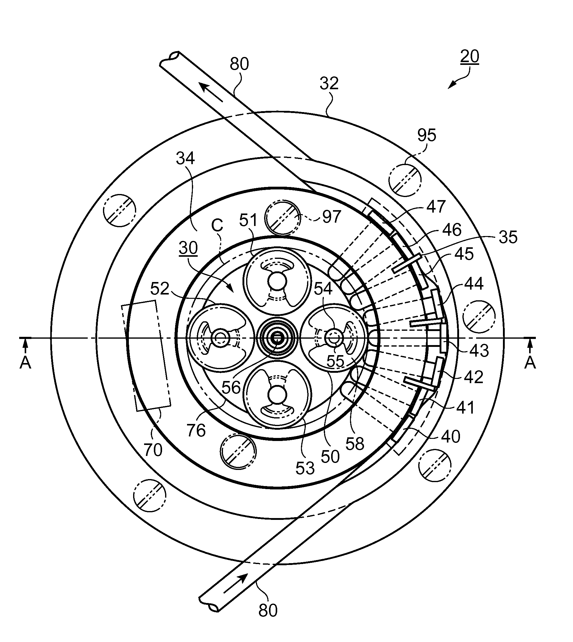
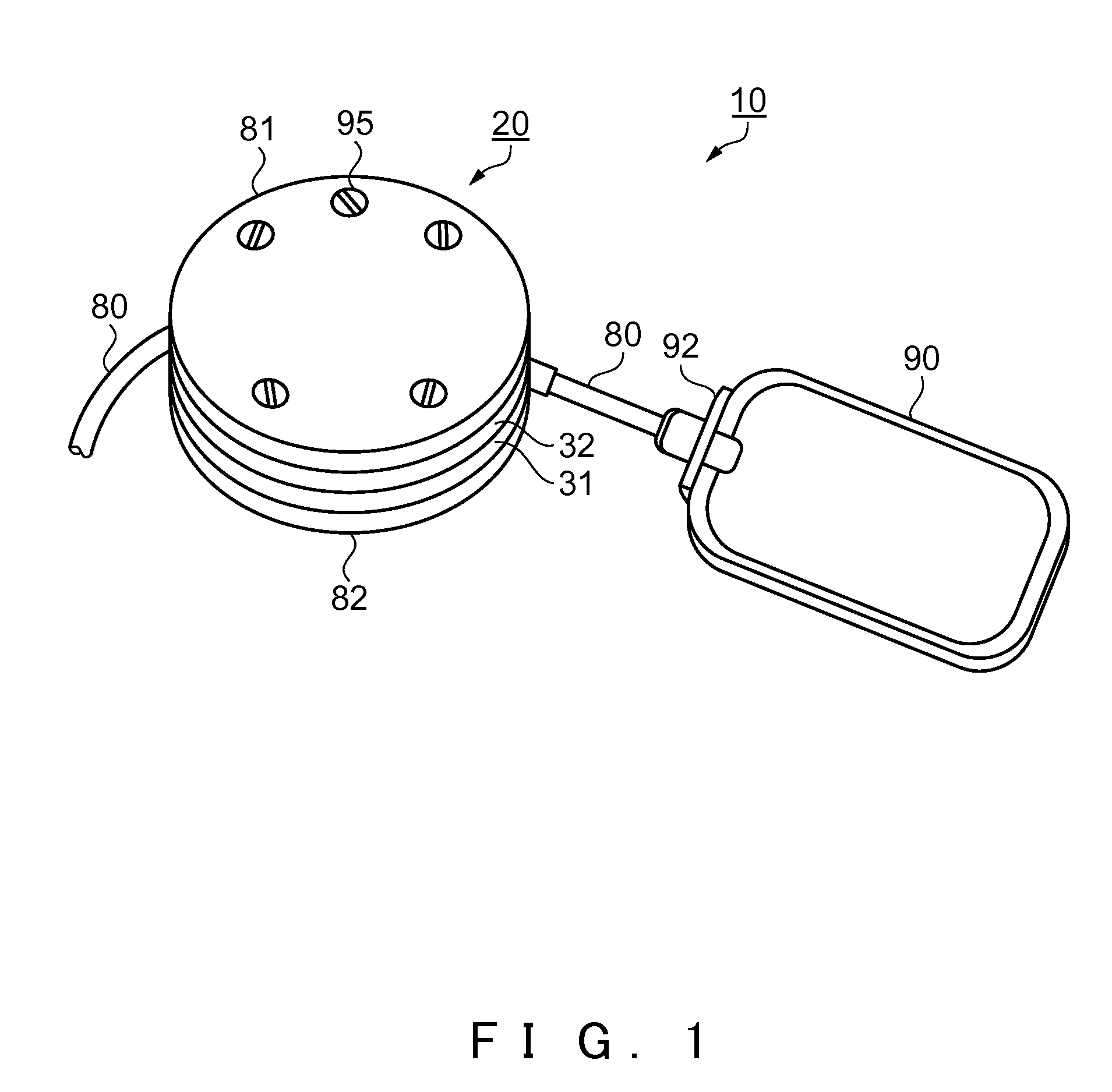
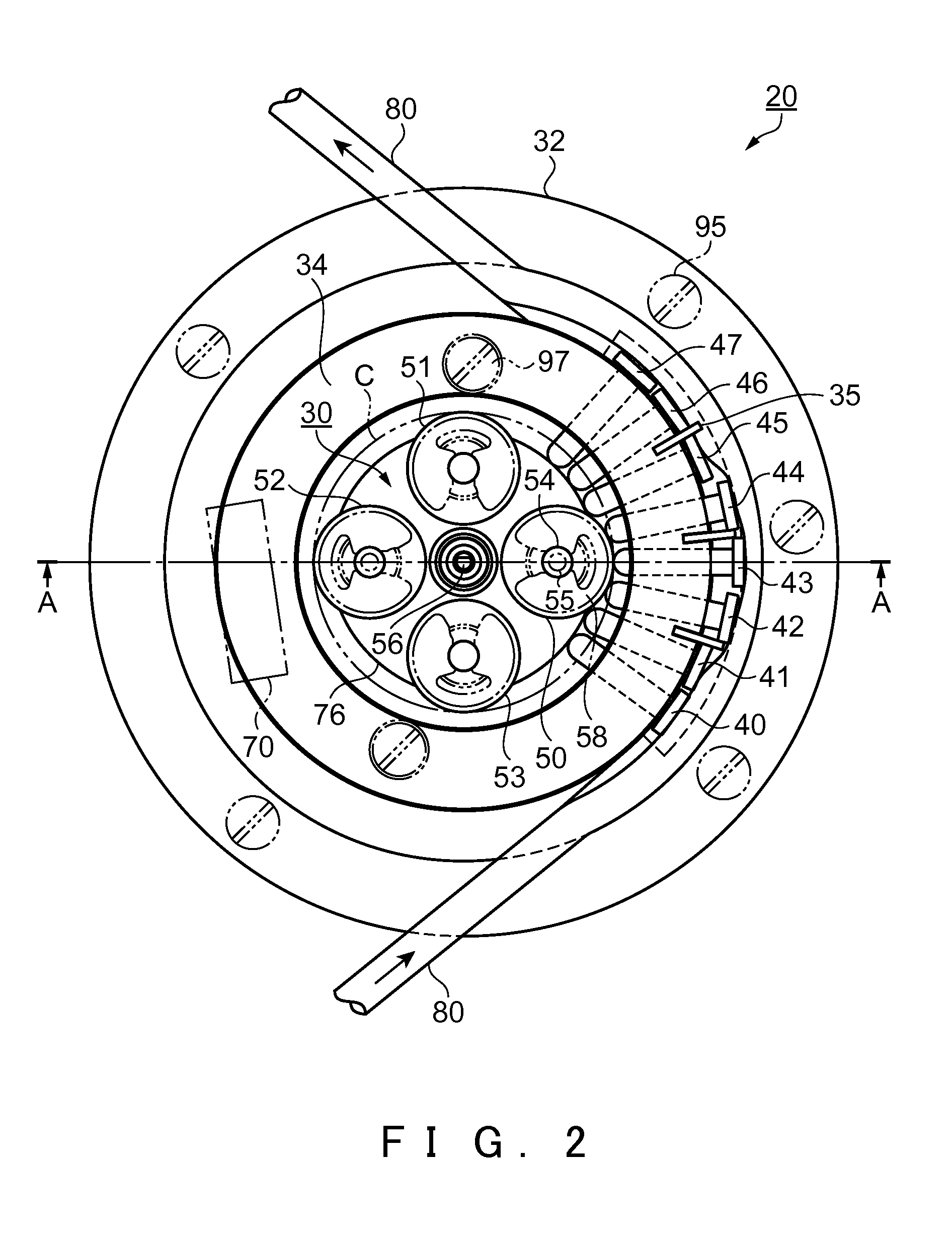
[0032]FIG. 1 to FIG. 3 show the fluid transporter and the fluid transporting device according to Mode of Embodiment 1.

[0033]FIG. 1 is a perspective view showing a constitution of the fluid transporter of Mode of Embodiment 1. In FIG. 1, a fluid transporter 10 is constituted of a fluid transporting device 20 for transporting a fluid by writhing motions, and a pack-shaped fluid storing container 90 for storing the fluid. Moreover, the fluid transporting device 20 and the fluid storing container 90 are made to communicate with each other by a tube 80.

[0034]The fluid storing container 90 is made of a flexible synthetic resin and formed, in this mode of embodiment, of a silicone-family resin. The fluid storing container 90 is provided at its one end portion with a tube holding portion 92, in which the tube 80 is so hermetically fixed by means such as a press fit such as solvent weld or adhesion that the flui...

embodiment 2

[0077]In Mode of Embodiment 2 thus far described (as referred to FIGS. 4 and 5), the rotary push plate 100 is mounted on the roller shaft 54 acting as a guide shaft, but can be directly mounted on the roller support pin 55. Moreover, the object of the invention can also be achieved, even if the four roller shafts or roller support pins are reduced to two (or a pair or) diagonal ones.

[0078]Moreover, the rotary push plate 100 and the rotary disc 76 can also be made integral. As in Mode of Embodiment 1, the structure can be provided with the four rotary push plates corresponding to the rollers 50 to 53. In addition, the rotary push plate can also be provided with two or three push portions.

[0079]Thus, the structure of the fluid transporting device 20 can be made simpler to reduce the cost.

[0080]Next, Mode of Embodiment 3 of the invention is described with reference to the accompanying drawing. Modes of Embodiments 1 and 2 thus far described have the structure, in which the fluid transp...

embodiment 3

[0086]According to Mode of Embodiment 3 thus far described, therefore, the pump unit 30 and the fluid storing portion 190 are arranged to have no overlap, so that the size can be reduced without increasing the thickness. Moreover, the casings for the pump unit 30 and the fluid storing portion 190 are formed into one, so that the cost can be reduced.

[0087]Here, the invention should not be limited to the foregoing mode of embodiments, but could contain modifications and improvements within the scope to achieve the object of the invention.

[0088]In Mode of Embodiment 1 to Mode of Embodiment 3 thus far described, for example, the fluid flow rate (or the transportation rate) can be set by setting the number of rollers, the number of push portions of the rotary disc and so on arbitrarily. However, the rotating speed of the rotary disc 76 can also be selected by storing the not-shown drive control circuit with a plurality of pieces of information capable of selecting the rotating speed arbi...


PUM


Abstract

A fluid transporting device is of a writhing type for transporting a fluid continuously. The fluid transporting device comprises a plurality of push pins arranged along a tube and radially on a concentric arc for squeezing a portion of the tube through which the fluid is fed and having elasticity substantially at right angles, and rollers for pushing those push pins sequentially from the inlet side to the outlet side of the fluid. With this structure, it is possible to provide a thin, small fluid transporting device for continuing a stable flow rate, and a fluid transporter having the fluid transporting device.

Description

[0001]This application is a divisional of U.S. patent application Ser. No. 11 / 795,994 filed on Sep. 28, 2007, which is a National Stage of PCT / JP2006 / 301398 filed Jan. 24, 2006. This application claims the benefit of Japanese Patent Application No. 2005-017932 filed Jan. 26, 2005. The disclosures of the above applications are incorporated herein by reference.TECHNICAL FIELD[0002]The present invention relates to a fluid transporting device and a fluid transporter provided with the fluid transporting device.BACKGROUND ART[0003]In the prior art, as a first conventional technique, there is known a tube pump (JP-A-10-220357) as a fluid transporting device of a writhing type, in which a tube for feeding a fluid is interposed between a plurality of rollers mounted on a concentric circle of the circumferential edge portion of a rotor and a tube receiving member, so that the rollers are caused to push the tube sequentially by rotating the rotor thereby to feed the fluid.[0004]As a second con...

Claims


Application Information

Patent Timeline
Patent Type & Authority Applications(United States)
IPC IPC(8): F04B43/12A61M5/142F04B43/08
CPCA61M5/14232F04B43/082F04B43/1223F04B43/1253F04B43/12
Inventor MIYAZAKI, HAJIMEKAWASUMI, KAZUOUSHIKOSHI, KENICHI
Owner SEIKO EPSON CORP
Why Eureka
Try Eureka