Core wire contact detection device

Inactive Publication Date: 2010-04-01
SHIN MEIWA IND CO LTD
View PDF5 Cites 10 Cited by
  • Summary
  • Abstract
  • Description
  • Claims
  • Application Information

AI Technical Summary

Benefits of technology

[0018]Accordingly, even when any of the strip blades is in contact with

Problems solved by technology

Accordingly, how to establish th

Method used


Image

  • Core wire contact detection device
  • Core wire contact detection device
  • Core wire contact detection device

Examples


Example

[0051]Hereinafter, an electric wire strip processing device according to a preferred embodiment will be described.

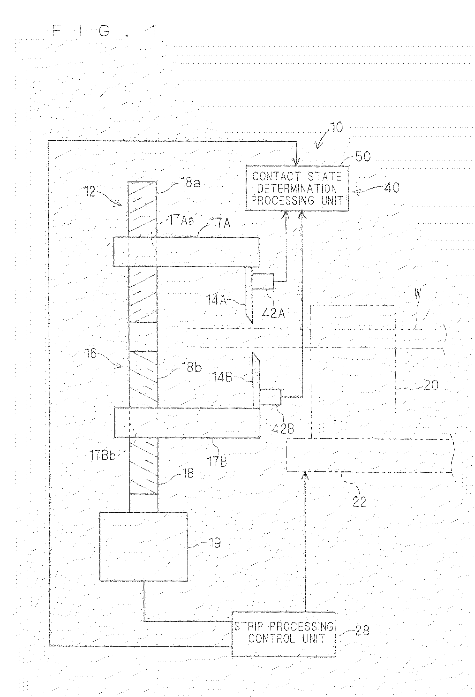
[0052]FIG. 1 is a schematic side view showing an electric wire strip processing device 10. The electric wire strip processing device 10 includes an electric wire strip unit 12 and a core wire contact detection device 40.

[0053]The electric wire strip unit 12 is a device for peeling a sheath Wb at an end portion of an electric wire W, and includes a pair of strip blades 14A and 14B, a blade drive unit 16, an electric wire holding unit 20 and a sheath removing drive unit 22.

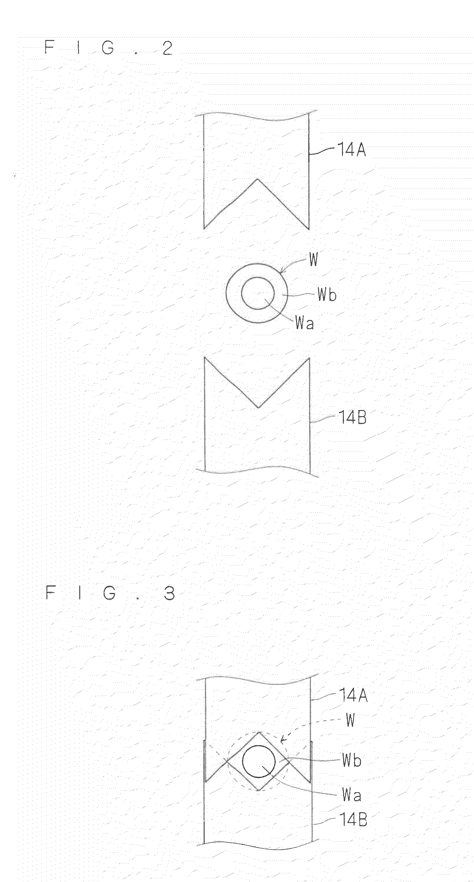
[0054]The pair of strip blades 14A and 14B are formed into a blade shape so as to cut into the sheath Wb of the electric wire W. For example, a polyvinyl chloride member is used for the sheath Wb. Here, the pair of strip blades 14A and 14B are formed into a shape of V-shaped blade in which tip portions thereof are dented in a substantially V-shape (see FIG. 2). The parts in shape of the V-shaped blade ar...


PUM

PropertyMeasurementUnit
Frequencyaaaaaaaaaa
Frequencyaaaaaaaaaa
Frequencyaaaaaaaaaa

Abstract

Provided is a core wire contact detection device which detects contact between a strip blade and a core wire when a sheath of an electric wire is stripped by the strip blade. The core wire contact detection device includes a vibration detection unit capable of detecting a vibration in a frequency range including a vibration frequency generated due to the contact between the core wire and the strip blade, and a contact state determination processing unit which determines that the strip blade and the core wire are in contact with each other when an amplitude of the detected vibration exceeds a predetermined threshold value.

Description

BACKGROUND OF THE INVENTION[0001]1. Field of the Invention[0002]The present invention relates to a technology of detecting contact between a strip blade and a core wire when a sheath of an electric wire is stripped.[0003]2. Description of the Background Art[0004]A sheath of an electric wire is generally stripped using a strip blade. If the strip blade is in contact with the core wire when the strip blade is being engaged in the sheath of the electric wire, the core wire is accidentally damaged.[0005]Conventionally, Japanese Patent Application Laid-Open No. 06-253430 (1994) discloses a technology of detecting contact between the strip blade and the core wire when the sheath of the electric wire is stripped.[0006]In the technology disclosed in Japanese Patent Application Laid-Open No. 06-253430 (1994), whether or not the strip blade and the core wire of the electric wire are in conduction is detected when the sheath of the electric wire is stripped, to thereby detect the contact betwe...

Claims


Application Information

Patent Timeline
IPC IPC(8): B26D7/27H02G1/12
CPCH02G1/1253H01R2201/20Y10T83/85Y10T83/853
Inventor YANO, TETSUYAOOSHIMA, TAKASHIOHSUMI, NOBUTAKA
Owner SHIN MEIWA IND CO LTD
Why Eureka
Try Eureka