Inter-stage attemperation system and method

a technology of attemperation system and temperature control, applied in the direction of water feed control, machines/engines, lighting and heating apparatus, etc., can solve the problems of temperature overshoot, adverse effects on steam turbines, shortening life cycles,

Active Publication Date: 2010-04-01
GENERAL ELECTRIC CO
View PDF11 Cites 43 Cited by
  • Summary
  • Abstract
  • Description
  • Claims
  • Application Information

AI Technical Summary

Problems solved by technology

If the exhaust steam from the superheaters reaches high enough temperatures, the steam turbine, as well as other equipment downstream of the HRSG, may be adversely affected.
For instance, high cyclic thermal stress in the steam piping and steam turbine may eventually lead to shor

Method used


Image

  • Inter-stage attemperation system and method
  • Inter-stage attemperation system and method
  • Inter-stage attemperation system and method

Examples


Embodiment Construction

[0012]One or more specific embodiments of the present invention will be described below. In an effort to provide a concise description of these embodiments, all features of an actual implementation may not be described in the specification. It should be appreciated that in the development of any such actual implementation, as in any engineering or design project, numerous implementation-specific decisions must be made to achieve the developers' specific goals, such as compliance with system-related and business-related constraints, which may vary from one implementation to another. Moreover, it should be appreciated that such a development effort might be complex and time consuming, but would nevertheless be a routine undertaking of design, fabrication, and manufacture for those of ordinary skill having the benefit of this disclosure.

[0013]When introducing elements of various embodiments of the present invention, the articles “a,”“an,”“the,” and “said” are intended to mean that ther...


PUM


Abstract

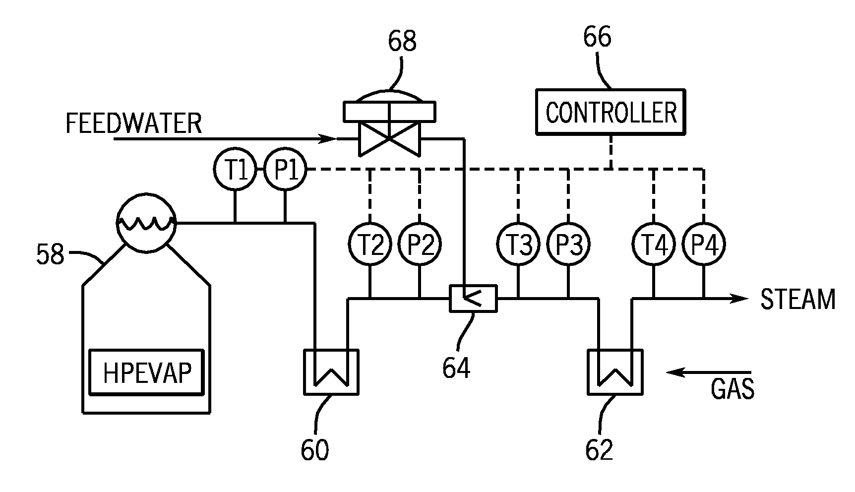
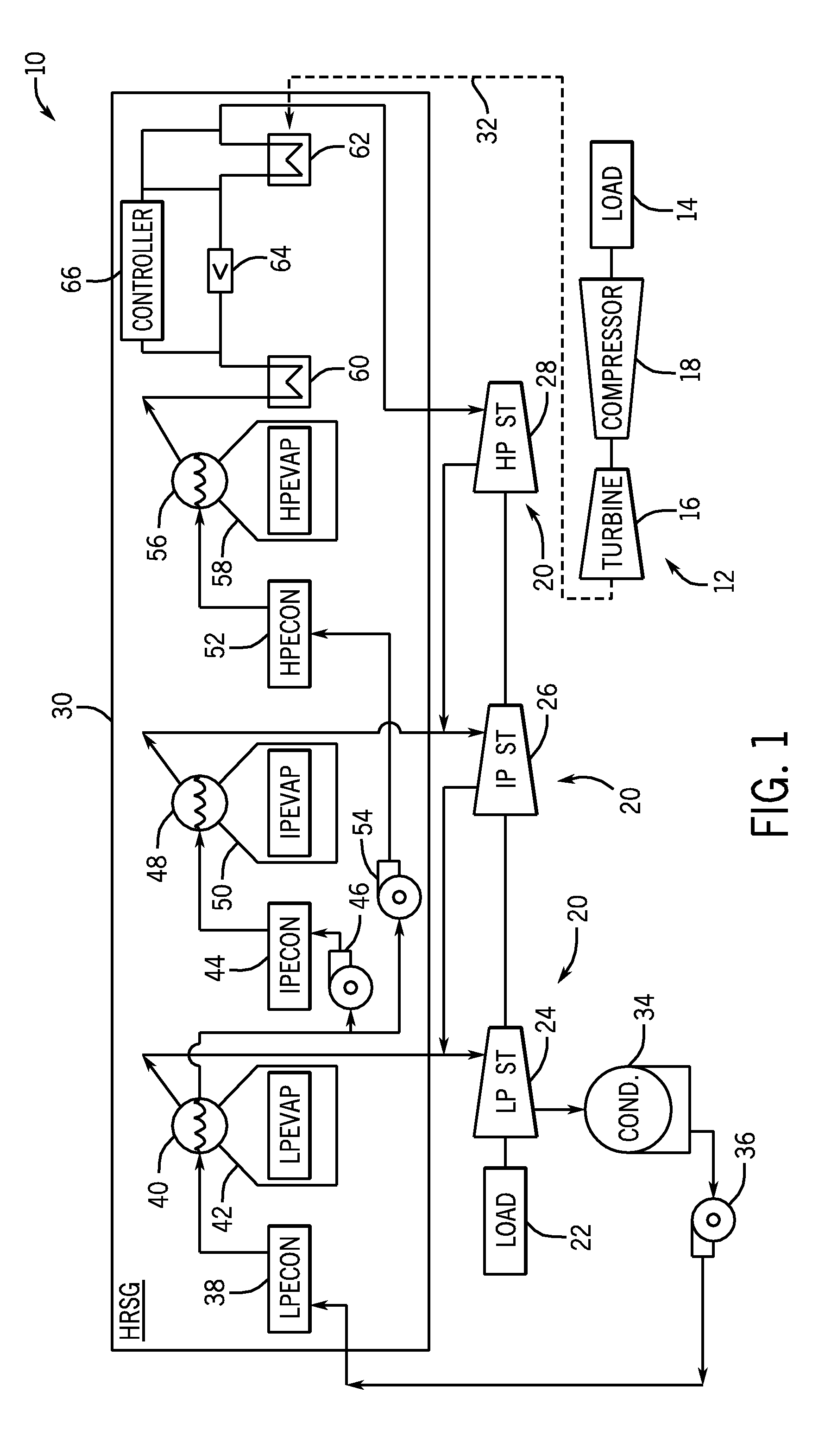
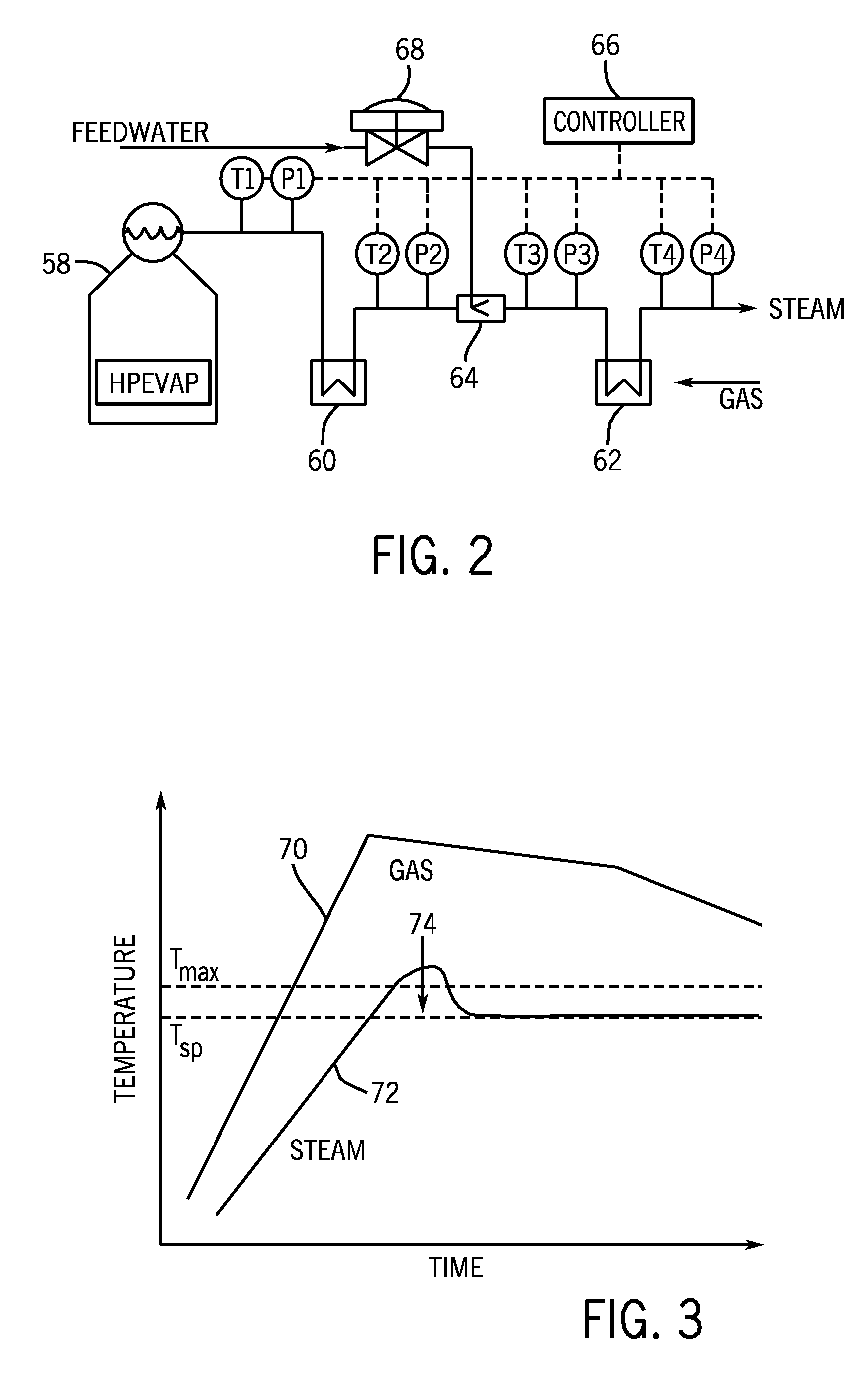
Systems and methods for controlling exhaust steam temperatures from a finishing superheater are provided. In certain embodiments, the system includes a controller which includes control logic for predicting an exhaust temperature of steam from the finishing superheater using model-based predictive techniques (e.g., based on empirical data or thermodynamic calculations). Based on the predicted exhaust temperature of steam, the control logic may use feed-forward control techniques to control the operation of an inter-stage attemperation system upstream of the finishing superheater. The control logic may determine if attemperation is required based on whether the predicted exhaust temperature of steam from the finishing superheater exceeds a set point temperature as well as whether the inlet temperature of steam into the finishing superheater drops below a set point temperature of steam. The attemperation system may include a characterizing function to linearize the valve operation controlled by the control logic to inject cooled, high-pressure feedwater into the steam upstream of the finishing superheater, which may, in turn, control the exhaust temperature of steam from the finishing superheater. The disclosed embodiments may also be applied to any systems where an outlet temperature of a fluid from a heat transfer device may be controlled.

Description

BACKGROUND OF THE INVENTION[0001]The present invention relates generally to model-based predictive control of temperatures. More specifically, the invention relates to model-based predictive temperature control of steam in relation to inter-stage attemperation, which may be used in heat recovery steam generation (HRSG) systems in combined cycle power generation applications.[0002]HRSG systems may produce steam with very high exhaust temperatures. In particular, HRSG systems may include superheaters through which steam may be superheated before being used by a steam turbine. If the exhaust steam from the superheaters reaches high enough temperatures, the steam turbine, as well as other equipment downstream of the HRSG, may be adversely affected. For instance, high cyclic thermal stress in the steam piping and steam turbine may eventually lead to shortened life cycles. Conventional control systems have been devised to help monitor and control the temperature of exhaust steam from HRSG...

Claims


Application Information

Patent Timeline
IPC IPC(8): F22G5/12
CPCF22G5/12F01K7/06
Inventor KUMAR, RAJEEVAKIRCHHOF, DARRIN GLENSMITH, GORDON RAYMONDCARBERG, WILLIAM GEORGE
Owner GENERAL ELECTRIC CO
Why Eureka
Try Eureka