Backlight Control System and Method

Active Publication Date: 2010-04-01
HIMAX TECH LTD
View PDF7 Cites 6 Cited by
  • Summary
  • Abstract
  • Description
  • Claims
  • Application Information

AI Technical Summary

Benefits of technology

[0008]In view of the foregoing, it is an object of the present invention to provide a backlight control system and method that increases response time without substantially increasing the cost.
[0009]According to one embodiment, an overdrive device modifies a backlight duty signal according to a current-frame backlight duty signal and a previous-frame backlight duty signal. In the embodiment, the overdrive device is implemented by a lookup table that outputs the modified backlight duty signal. The backlight driven by the modified backlight duty signal then emits light to a display panel, thereby increasing response time of the backlight.

Problems solved by technology

The constant backlight approach has poor dynamic contrast.
Nevertheless, a normal cold cathode fluorescent lamp (CCFL) has a low response time.
The low response-time problem may only be solved by replacing the normal but low-price CCFL with a fast-response but expensive CCFL.
However, such solution is not practical to mass production considering the cost and the acceptance of general users.

Method used


Image

  • Backlight Control System and Method
  • Backlight Control System and Method
  • Backlight Control System and Method

Examples


Embodiment Construction

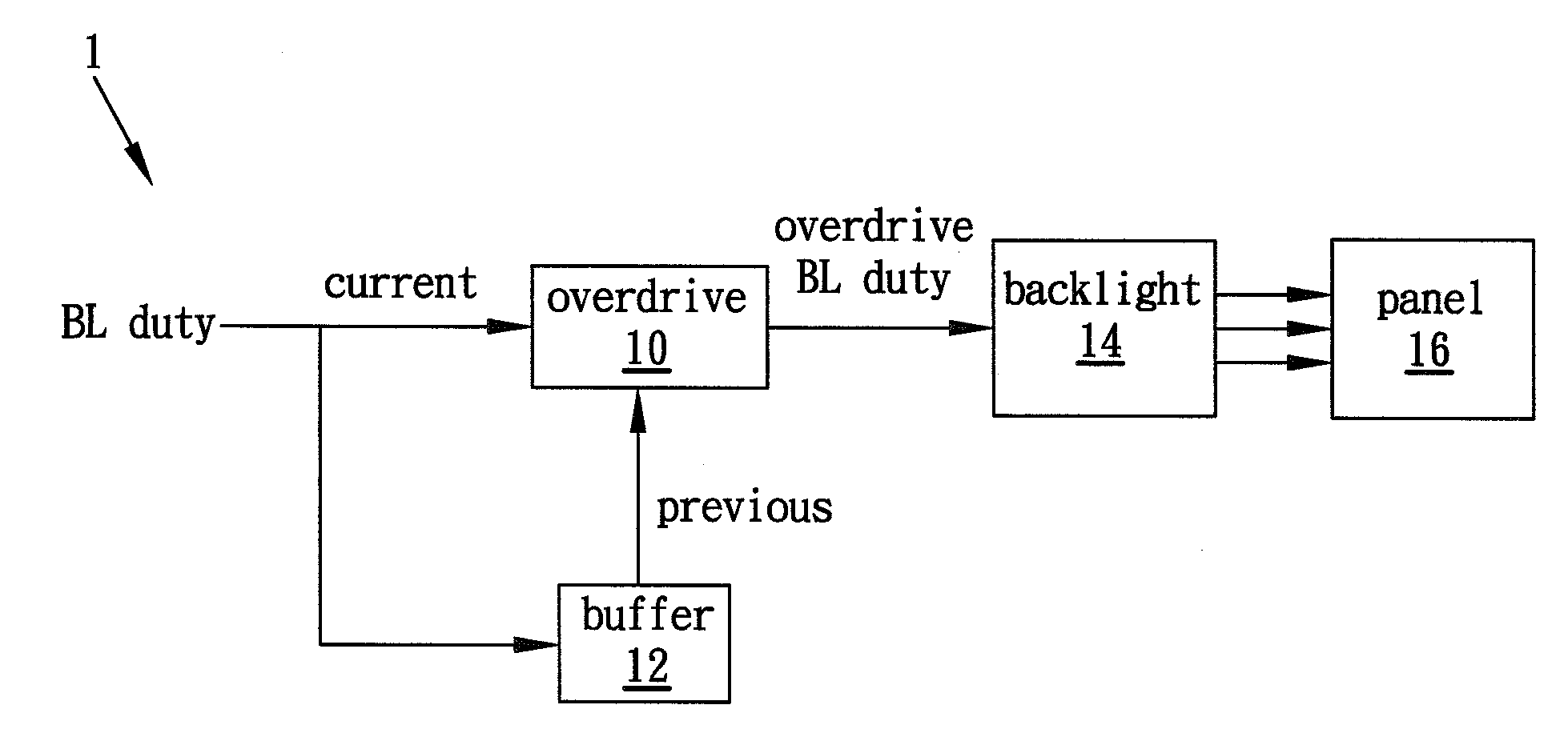
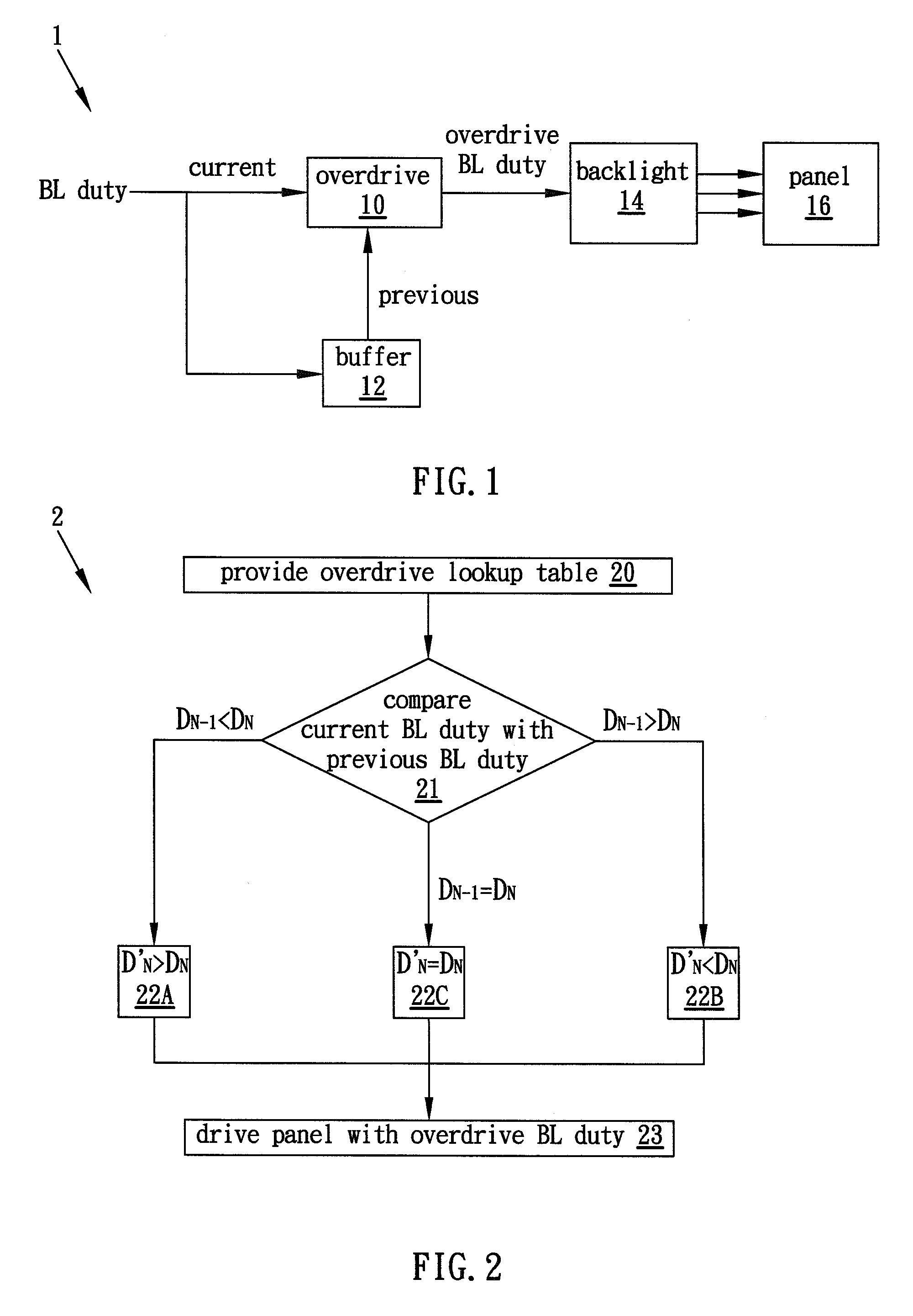
[0013]FIG. 1 illustrates a dynamic backlight overdrive control system 1 according to one embodiment of the present invention. FIG. 2 illustrates a dynamic backlight overdrive control method 2 according to the embodiment of the present invention. Due to the low-speed light source, such as one or more of a cold cathode fluorescent lamp (CCFL), a low-speed light-emitting diode (LED), and some other low-end light source, an overdrive device 10 is utilized, in the embodiment, to accelerate the overall response time of the backlight control system 1. The overdrive device 10 may be implemented by one or more of a hardware circuit and a software program.

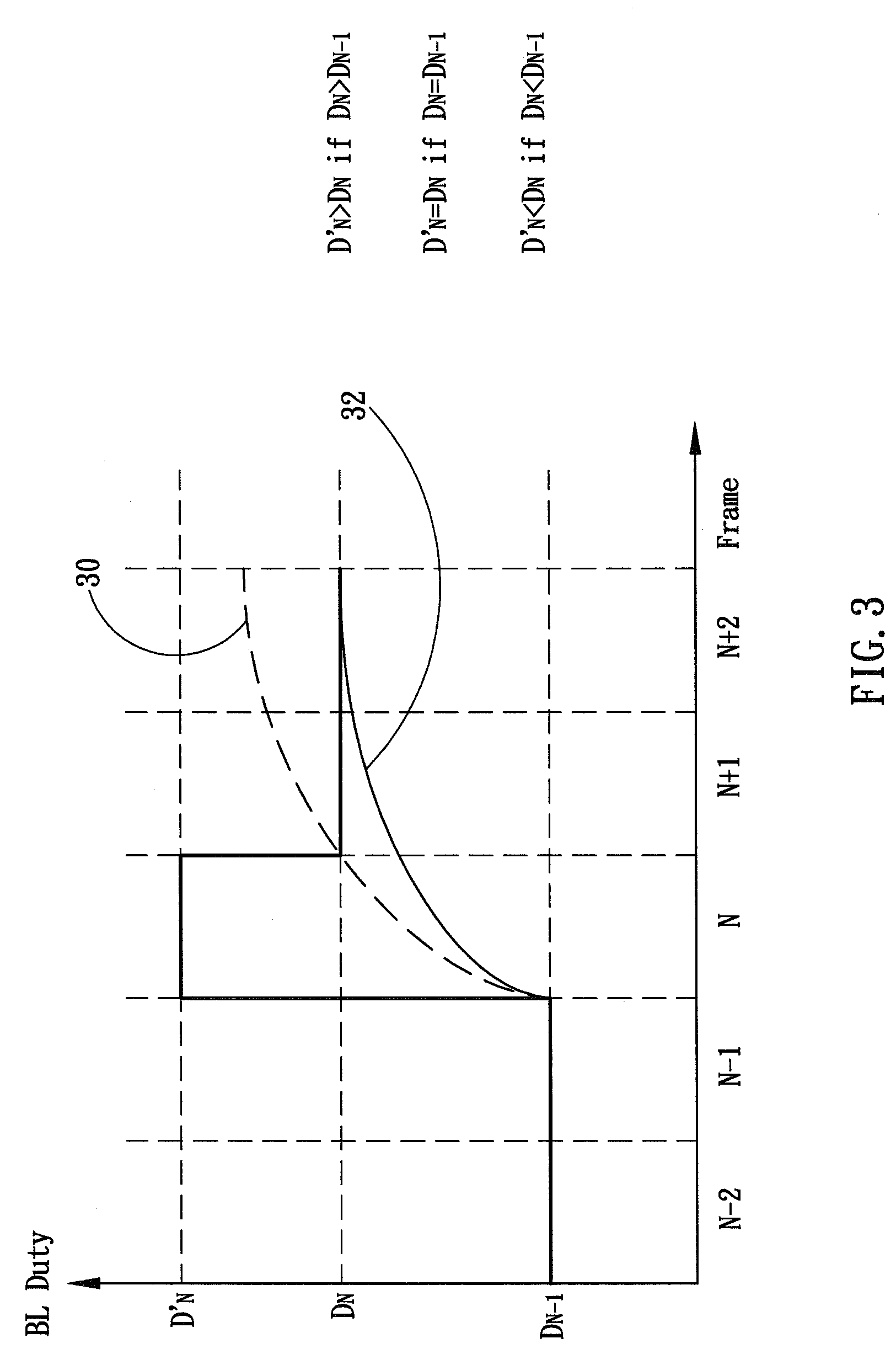
[0014]In the illustrated embodiment, a lookup table, such as exemplified in, but not limited to, the following Table 1 is provided (step 20). The lookup table may comprise, for example, an overdrive table that outputs an overdrive backlight duty signal (BL duty) based on a current backlight duty signal and a previous backlight duty signal, w...


PUM


Abstract

A backlight control system and method are disclosed. An overdrive device modifies a backlight duty signal according to a current-frame backlight duty signal and a previous-frame backlight duty signal. In one embodiment, the overdrive device is implemented with a lookup table that outputs the modified backlight duty signal. The backlight driven by the modified backlight duty signal then emits light to a display panel, thereby increasing a response time of the backlight.

Description

BACKGROUND OF THE INVENTION[0001]1. Field of the Invention[0002]The present invention generally relates to backlight control, and more particularly to a backlight control system and method using an overdrive lookup table.[0003]2. Description of the Prior Art[0004]Backlight is used to illuminate a flat panel display, such as a liquid crystal display (LCD), from the back or side of the flat panel display. The light source may be a cold cathode fluorescent lamp (CCFL), a light-emitting diode (LED) or another light source.[0005]A constant backlight is the backlight that outputs even and constant light no matter how the image data or the ambient light has been changed. The constant backlight approach has poor dynamic contrast. In order to increase the contrast, a dynamic backlight (DBL) is thus disclosed to dynamically or adaptively adjust (overall or respective portions of) the backlight brightness in accordance with image data distribution.[0006]Nevertheless, a normal cold cathode fluo...

Claims


Application Information

Patent Timeline
IPC IPC(8): G09G5/10
CPCG09G3/3406G09G2320/064G09G2360/16G09G2340/16G09G2320/0646
Inventor CHEN, SHING-CHIA
Owner HIMAX TECH LTD
Why Eureka
Try Eureka