Drop on demand print head with fluid stagnation point at nozzle opening

Inactive Publication Date: 2007-12-20
EASTMAN KODAK CO
View PDF20 Cites 69 Cited by
  • Summary
  • Abstract
  • Description
  • Claims
  • Application Information

AI Technical Summary

Benefits of technology

[0006]It is possible to reduce this limitation by having a continuous flow of fluid from behind each orifice. Continuous fluid flow internal to the system decreases the time to refill the fire chamber directly behind the nozzle opening after droplet ejection. This in turn dramatically increases the response time of the system.

Problems solved by technology

This in turn dramatically increases the response time of the system.

Method used


Image

  • Drop on demand print head with fluid stagnation point at nozzle opening
  • Drop on demand print head with fluid stagnation point at nozzle opening
  • Drop on demand print head with fluid stagnation point at nozzle opening

Examples


Embodiment Construction

[0012]The present description will be directed in particular to elements forming part of, or cooperating more directly with, apparatus in accordance with the present invention. It is to be understood that elements not specifically shown or described may take various forms well known to those skilled in the art.

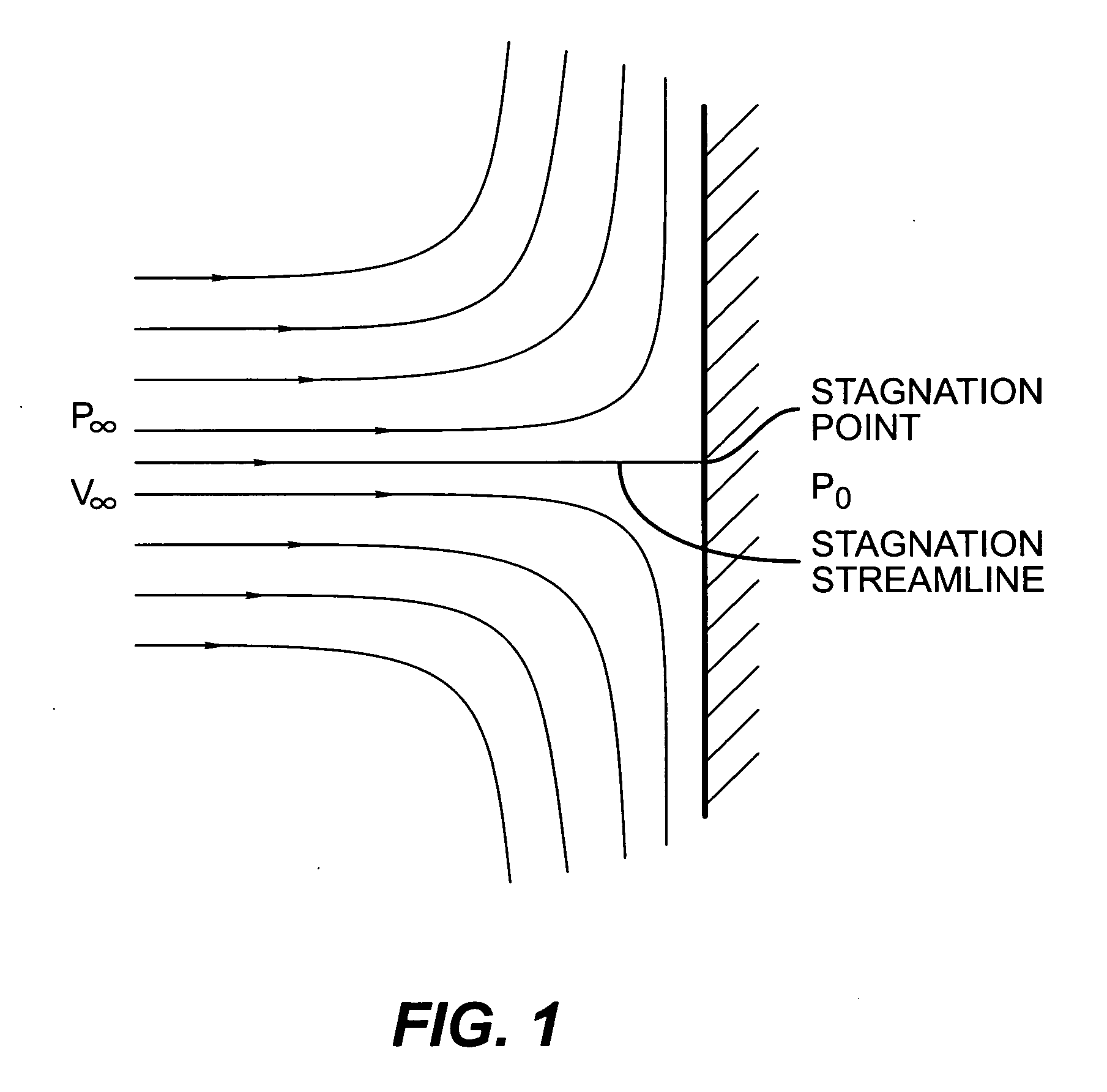
[0013]Bernoulli's equation states:

P+½ρV2+ρgh=constant,

where p is pressure, ρ is density, V is velocity, h is elevation, and g is gravitational acceleration. When a steady flow impinges on a perpendicular plate, as shown in FIG. 1, there is one streamline that divides the flow in half. Above this streamline, all the flow goes over the plate, and below this streamline all the flow goes under the plate. Along this dividing streamline, the fluid moves towards the plate. Since the flow cannot pass through the plate, the fluid must come to rest at the point where it meets the plate. In other words, the fluid “stagnates.” The fluid along the dividing, or stagnation, streamline slows ...


PUM


Abstract

A drop on demand ink jet print head has a chamber with a plurality of liquid passages into and out of said chamber, such that liquid is continuously moved into the chamber to a stagnation point adjacent to the nozzle opening, whereat the fluid comes substantially to rest, and out of the chamber from the stagnation point such that vector sum of liquid flow derived forces within the liquid channels is neutral. An actuator associated with the chamber is adapted to selectively increase the pressure of the liquid at the stagnation point to thereby eject a liquid drop from the nozzle opening. Continuous fluid flow internal to the system decreases the time to refill the fire chamber directly behind the nozzle opening after droplet ejection. This in turn dramatically increases the response time of the system.

Description

FIELD OF THE INVENTION[0001]The present invention relates to the field of drop on demand inkjet printers, and more particularly to the improvement in ejection frequency and response time of such drop on demand printing systems.BACKGROUND OF THE INVENTION[0002]Traditionally, digitally controlled color ink jet printing is accomplished by one of two technologies; “continuous stream” or “drop on demand.” In both, liquid, such as ink, is fed through channels formed in a print head. Each channel includes a nozzle from which droplets are selectively extruded and deposited upon a recording surface. Continuous stream printing uses a pressurized liquid source that produces a stream of droplets that are selectively steered toward a recording surface to imagewise deposit thereon, or are captured to be recycled.[0003]On the other hand, drop on demand printing, provides droplets for impact upon a recording surface. Selective activation of an actuator causes the formation and ejection of a flying ...

Claims


Application Information

Patent Timeline
IPC IPC(8): B41J2/045
CPCB41J2/04B41J2202/12B41J2002/14419B41J2/14
Inventor BAUMER, MICHAEL F.PIATT, MICHAEL J.XIE, YONGLIN
Owner EASTMAN KODAK CO
Why Eureka
Try Eureka