Image display apparatus and image display method

a technology of image display and subfield lighting, applied in the direction of instruments, television systems, static indicating devices, etc., to achieve the effect of reducing dynamic false contours, motion judder, or moving image blur, and reducing image degradation

Inactive Publication Date: 2010-04-01
HITACHI LTD
View PDF1 Cites 19 Cited by
  • Summary
  • Abstract
  • Description
  • Claims
  • Application Information

AI Technical Summary

Benefits of technology

[0018]According to the invention, a sub-field lighting image display apparatus is capable of displaying a frame-rate converted image by reducing

Problems solved by technology

However, the following problem was found when the frame rate conversion ON/OFF

Method used


Image

  • Image display apparatus and image display method
  • Image display apparatus and image display method
  • Image display apparatus and image display method

Examples


first embodiment

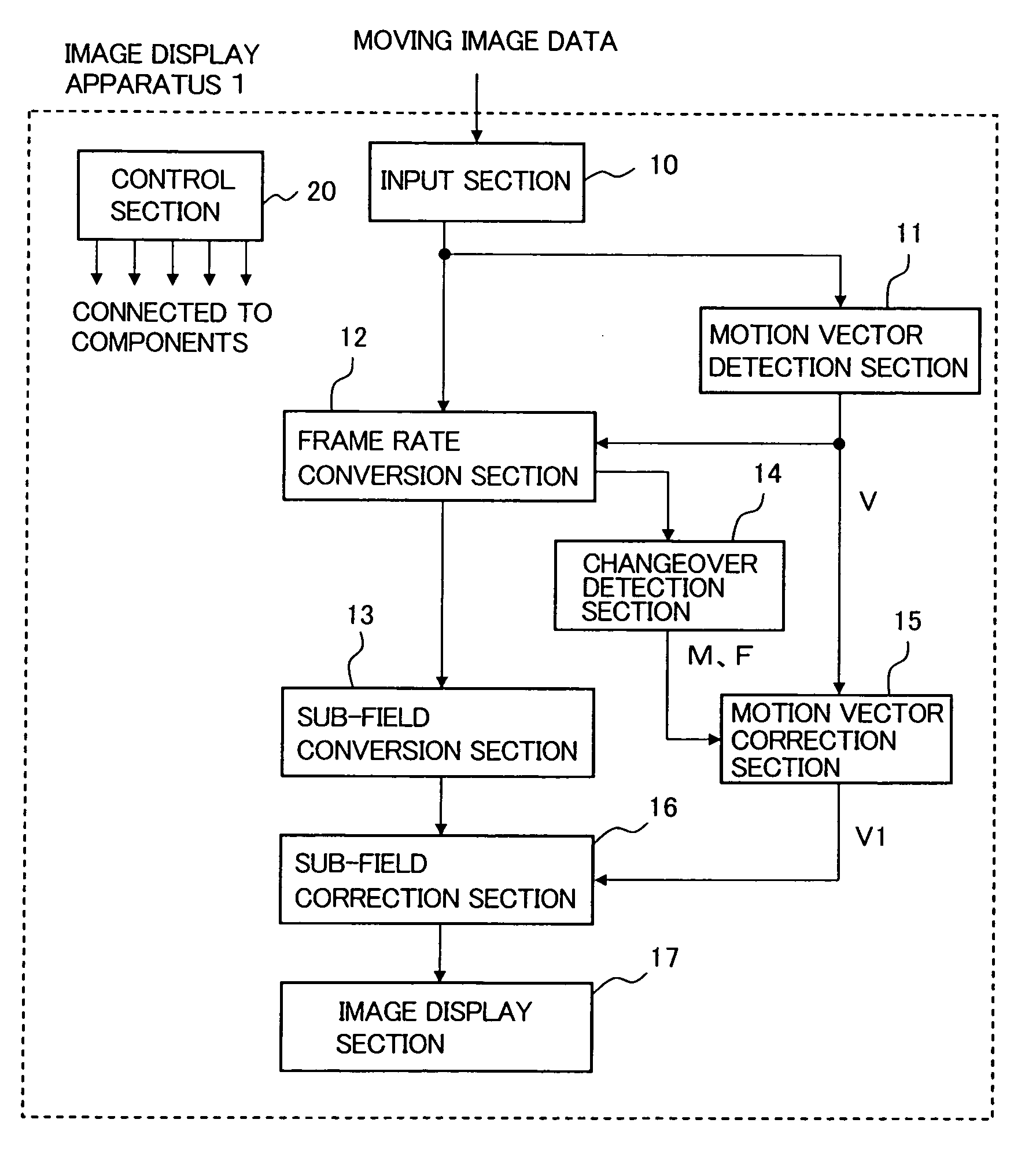
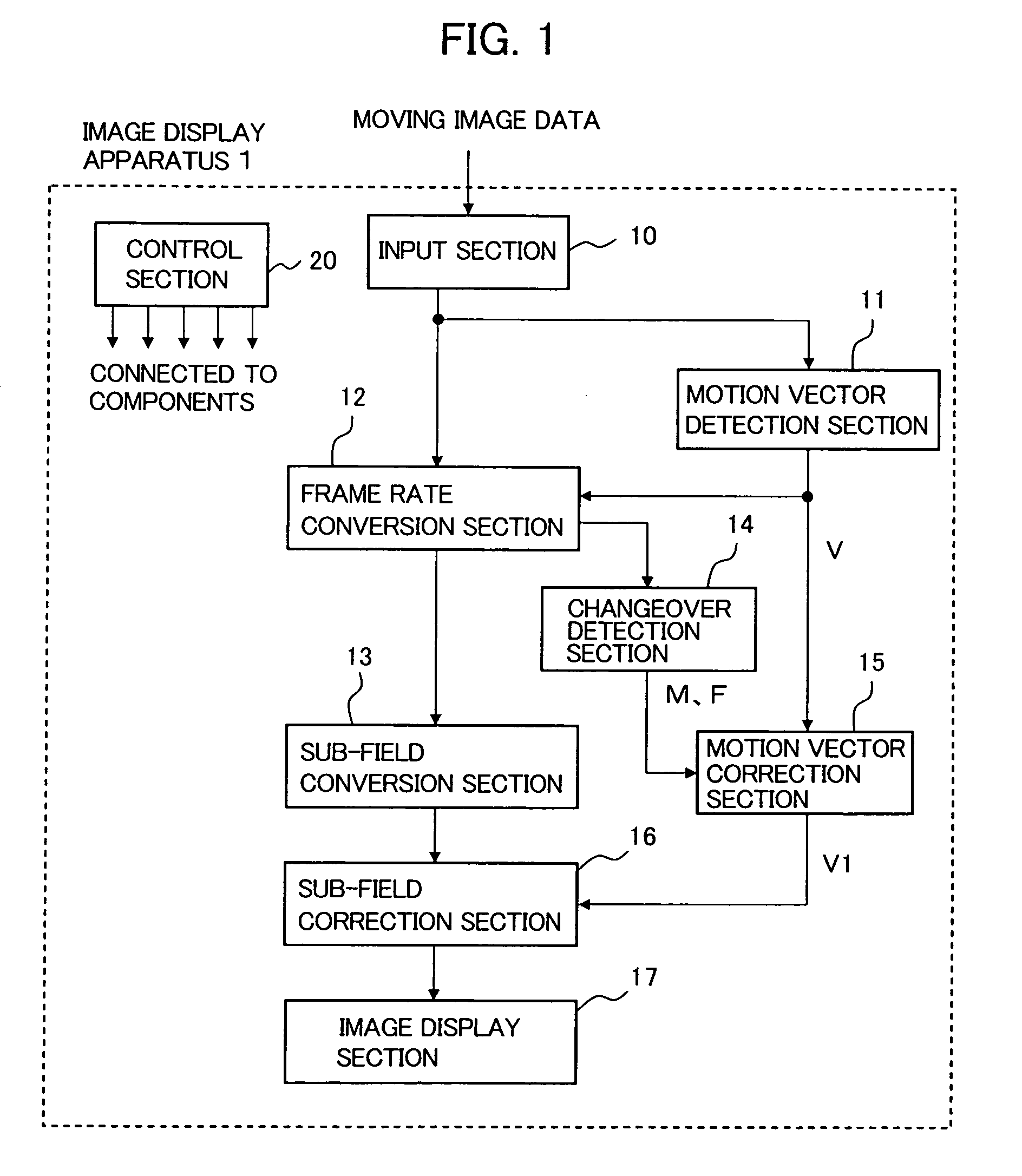
[0033]FIG. 1 is a block diagram showing the image display apparatus according to the first embodiment of the invention. An image display apparatus 1 includes an input section 10, a motion vector detection section 11, a frame rate conversion section 12, a sub-field conversion section 13, a changeover detection section 14, a motion vector correction section 15, a sub-field correction section 16, an image display section 17, and a control section 20.

[0034]The following describes the operation of each of the above sections. The input section 10 is supplied with moving image data. For example, the input section 10 may include an image input terminal or a network connection terminal or may include a TV broadcasting tuner. The input section 10 applies image preprocessing to the input moving image data as needed. The input section 10 outputs the processed display data to the motion vector detection section 11 and the frame rate conversion section 12.

[0035]The motion vector detection section...

second embodiment

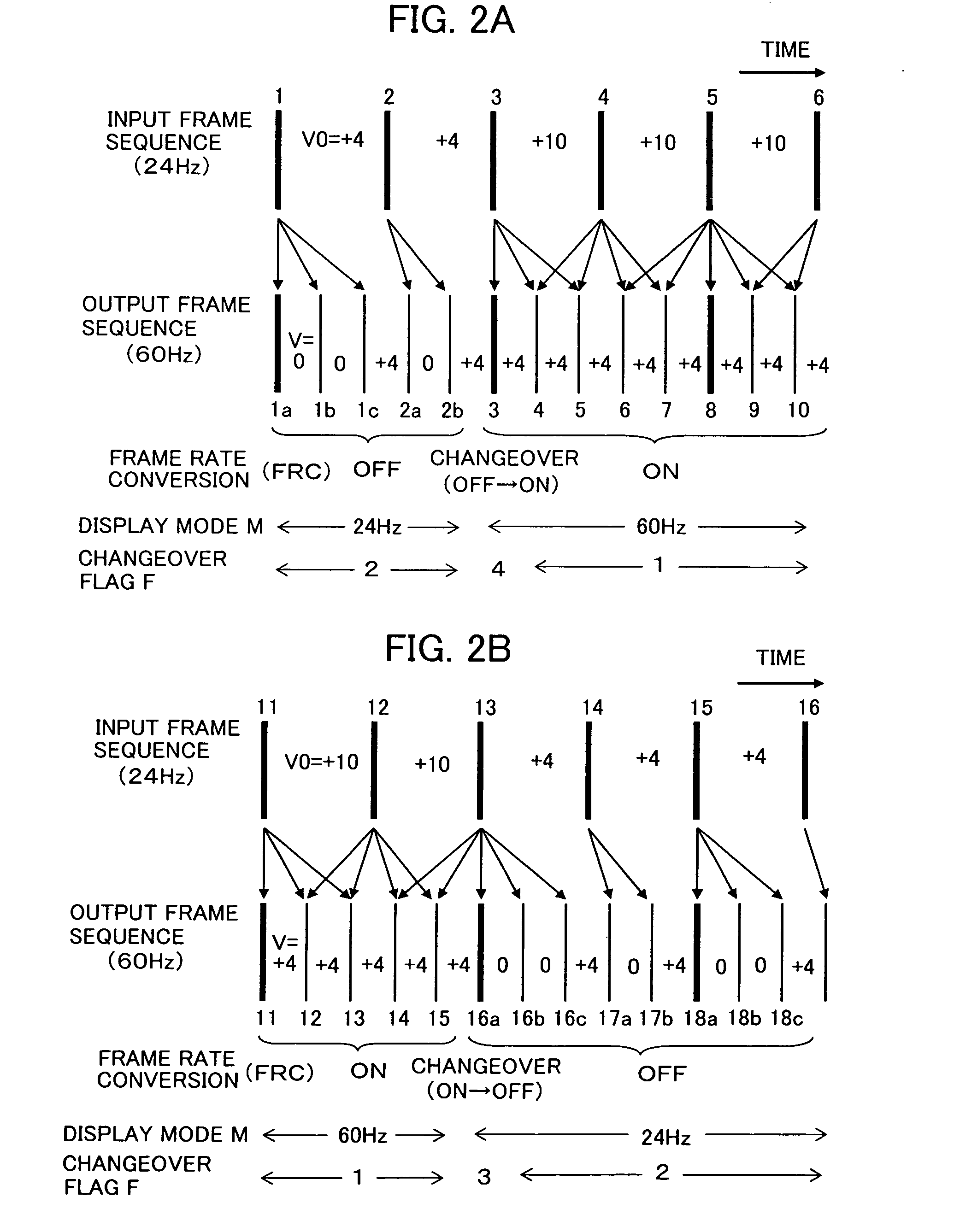
[0075]The image display apparatus according to the second embodiment has the same configuration as that shown in FIG. 1 according to the first embodiment except that operations of the motion vector correction section 15 are changed. When the frame rate conversion (FRC) changes its conversion mode from ON (first conversion mode) to OFF (second conversion mode) or from OFF to ON, an image motion may become discontinuous before and after the mode change and the image may oscillate. To solve this problem, the motion vector correction section 15 according to the second embodiment performs the correction so as to smooth a motion vector change when the FRC mode changes.

[0076]The sub-field correction section 16 relocates sub-fields using the corrected motion vector. Specifically, the motion vector correction section 15 assumes the correction (V×α) using the equation (1) to be correction amount 100%. The motion vector correction section 15 further adjusts the correction amount using an adjus...

third embodiment

[0091]FIG. 9 is a block diagram of the image display apparatus according to the third embodiment of the invention. The image display apparatus 1 according to the third embodiment is compliant with a modification of the configuration of FIG. 1 according to the first embodiment by removing the changeover detection section 14 and newly adding a frame rate conversion setup section 18.

[0092]The frame rate conversion setup section 18 is equivalent to one of television screen setup menus. The frame rate conversion setup section 18 allows a user to specify the frame rate conversion (FRC) mode ON or OFF using a remote controller. FRC setup value T is set to 1 when FRC=ON (first conversion mode) is selected. FRC setup value T is set to 2 when FRC=OFF (second conversion mode) is selected.

[0093]According to the FRC setup value T, the frame rate conversion section 12 changes the conversion operation, creates an interpolation frame, and outputs it. The information about the FRC setup value T is i...


PUM


Abstract

A sub-field lighting image display apparatus according to the present invention improves a dynamic false contour, motion judder, and the like occurring when displaying an image to which frame rate conversion is applied. A frame rate conversion section converts a frame rate for an input image. A motion vector detection section detects motion vector V0 between frames in the input image and finds motion vector V after the frame rate conversion based on the detected motion vector V0. When the frame rate conversion section repeatedly outputs the input image as an interpolation image, a motion vector correction section corrects the motion vector V to V1 using V1=V×α, where 0≦α<1. A sub-field conversion section converts each frame into luminescent data for multiple sub-fields. A sub-field correction section relocates the luminescent data for the sub-fields using the corrected motion vector V1.

Description

CLAIM OF PRIORITY[0001]The present application claims priority from Japanese patent application serial No. JP 2008-247968, filed on Sep. 26, 2008, the content of which is hereby incorporated by reference into this application.BACKGROUND OF THE INVENTION[0002](1) Field of the Invention[0003]The present invention relates to a sub-field lighting image display apparatus and an image display method for gradation display by time-sharing each of image frames created by frame rate conversion into multiple sub-fields.[0004](2) Description of the Related Art[0005]Frame rate conversion (frame count conversion) is needed when the frame rate of an input image signal differs from the display frame rate of an image display apparatus. The frame rate conversion preferably interpolates frames so that the image quality is prevented from degrading and an image continues to move smoothly between frames. A motion correcting frame count conversion method generates an interpolation frame signal by moving i...

Claims


Application Information

Patent Timeline
IPC IPC(8): G06T1/00H04N5/04G09G3/20G09G3/291
CPCG09G3/288G09G2320/0261H04N7/0127G09G2320/0606G09G2340/0435G09G2320/0266
Inventor HATTORI, HIDEHARUHAMADA, KOICHIFUKUDA, NOBUHIRONAKAJIMA, MITSUO
Owner HITACHI LTD
Why Eureka
Try Eureka